General Plan Correction List
A review of your plans has been performed. Items listed in this review require amended construction documents such as revised sealed plans, supplemental instructions, addenda, field orders, or change orders. All numbered review items must be addressed before plans approval will be issued. Marked up plans may be included to assist the design professional in identifying specific areas referenced in the review comments.
This project has/has not been reviewed under the Tennessee Public Buildings Accessibility Act. It is the responsibility of the owner and design professional to comply in full with accessibility codes and standards for the enforcement of the Tennessee Public Building Accessibility Act. TCA 68-120-204
In addition to the revised sealed plans, the designer may also provide a separate letter to explain the changes to the construction documents. All drawing revisions should be clouded with a corresponding revision number tag and be indicated on a drawing index.
Starting construction before plans approval may be considered as a just cause, by the State, to issue a stop work order. It will also compromise, if not prevent, the issuance of a Certificate of Occupancy upon completion of the project. Rule 0780-02-03-.10
Please note the following: When submitting documents using the Portal application it is important to use correct document type(s) that best match the documents being submitted, e.g. Sprinkler Shop Drawings, Energy Certificates, etc. In order to ensure an accurate and timely response to your submittal:
- Provide the Tennessee Fire Marshal’s TFM number and Project number on cover page of all plan sets and correspondence.
- Provide a corresponding letter which indicates, in the order of the review, where the revised items may be located on the drawings.
- Identify all corrections by means of a mark or cloud and provide only the sheets that require correction. If the number of corrections warrant complete revised sets of plans, revised sets are acceptable.
- Ensure that all revised documentation is sealed by the design professional of record.
- Document security settings must allow the application of markups and stamps, allow multiple PDF documents to be combined or merged into a single document, and allow the application of electronic signatures and certification.
- Use a standardized font recognized by Adobe Acrobat (such as Arial) to prevent loss of information during the conversion process from DWG to PDF.
All review items marked as stipulations must be satisfied by sealed construction documents before such work is performed.
New buildings shall have approved radio coverage for emergency responders within the building based upon the existing coverage levels of the public safety communication systems of the jurisdiction at the exterior of the building. In-building, two-way emergency responder communication coverage within the building shall be based on the existing coverage levels of the public safety communication systems utilized by the jurisdiction, measured at the exterior of the building. IFC 510.1
Exception: Where it is determined by the local fire chief in coordination with local law enforcement and EMS that the radio coverage system is not needed (C&I Rule 0780-02-02-.01(f)(1).
A Certificate of Occupancy will not be issued if stipulations are not satisfied in accordance with Rule 0780-02-03-.10.
Information to be Included on the Plan Drawings
Each review item to be addressed in the revised documents
General Requirements
- Provide a cover sheet or code data sheet. IBC 107.2.1
- List the codes the design conforms to. You may copy the following:
- International Building Code, 2021 edition
- International Fuel Gas Code, 2021 edition
- International Mechanical Code, 2021 edition
- International Plumbing Code, 2021 edition
- National Electric Code, NFPA 70, 2017 edition.
- International Energy Conservation Code, 2021 edition, or
- International Energy Conservation Code, 2006 edition (Group F-1, F-2, S-1, & S-2 Only)
- International Fire Code, 2021 edition.
- International Existing Building Code, 2021 edition (scope of work related to existing buildings)
- 2010 ADA Standards for Accessible Design (for buildings required to comply with Tennessee Public Building Accessibility Act) T.C.A § 68-120-204(a)(1)
- Amendments to the State Fire Marshal’s adopted codes are available at the Codes Enforcement Website.
- Provide the name and contact information of the registered design professional who shall act as the registered design professional in responsible charge for this project. IBC 107.3.4
- The plans are not properly sealed. The registrant shall superimpose his or her signature and date of signature across the face and beyond the circumference of the seal. A&E Rule 0120-02 Electronic signatures and dates of signature are not required to be placed across the face and beyond the circumference of the seal but must be placed adjacent to the seal. The design of the registrant’s seal required by T.C.A. § 62-2-306 shall be as follows:
- Modified sheets and/or design revisions are not properly sealed. When revisions are made to sealed documents, the revisions are to be resealed and dated to the most recent revision. A&E Rule 0120-02.
- Provide the building name, 911 street address (if one has been assigned), city and county. IBC 107.2.1
- Provide the IECC Climate Zone. Climate zones from Figure C301.1 or Table C301.1 shall be used for determining the applicable requirements from Chapter 4. Locations not indicated in Table C301.1 shall be assigned a climate zone in accordance with Section C301.3. IECC 301.1
- If a state agency will license the facility, identify the licensing agency and the license type.
- For all altered areas within an existing building, provide a key floor plan showing the suite(s) and altered areas relative to the entire building, and separate existing and proposed floor plans. Plans shall be dimensioned and drawn in a standard architectural or engineering scale.
- Provide an updatable “Index of Drawings” which reflects the most current drawing revision, and the date revised with each submission. IBC 107.2.1
- The following drawings were indexed but not provided with the submittal. IBC 107.2.1
- The following drawings were submitted but not shown in the Index of Drawings. IBC 107.2.1


Building Analysis
- Occupancy classification is the formal designation of the primary purpose of the building, structure or portion thereof. Structures shall be classified into one or more of the occupancy groups specified in this section based on the nature of the hazards and risks to building occupants generally associated with the intended purpose of the building or structure. Provide the use and occupancy classification in accordance with IBC 302.1.
- Assembly (Section 303): Groups A-1, A-2, A-3, A-4 and A-5
- Business (Section 304): Group B.
- Educational (Section 305): Group E.
- Factory and Industrial (Section 306): Groups F-1 and F-2.
- High Hazard (Section 307): Groups H-1, H-2, H-3, H-4 and H-5.
- Institutional (Section 308): Groups I-1, I-2, I-3 and I-4.
- Mercantile (Section 309): Group M.
- Residential (Section 310): Groups R-1, R-2, R-3 and R-4.
- Storage (Section 311): Groups S-1 and S-2.
- Utility and Miscellaneous (Section 312): Group U.
- An area, room or space that is intended to be occupied at different times for different purposes shall comply with all applicable requirements associated with such potential multipurpose. Structures containing multiple occupancy groups shall comply with Section 508. Where a structure is proposed for a purpose that is not specified in this section, such structure shall be classified in the occupancy it most nearly resembles based on the fire safety and relative hazard. IBC 302.1
- Occupied roofs shall be classified in the group that the occupancy most nearly resembles, according to the fire safety and relative hazard, and shall comply with Section 503.1.4.
- Each portion of a building shall be individually classified in accordance with Section 302.1. Where a building contains more than one occupancy group, the building or portion thereof shall comply with the applicable provisions of Section 508.2, 508.3, 508.4 or 508.5, or a combination of these sections. IBC 508.1
- List all the classifications contained in the structure.
- For multiple occupancies state whether the occupancies are separated or nonseparated.
- Identify if other occupancies are accessory to the main occupancy.
- For I-1, I-2, I-3, or R-4 occupancies, state the occupancy condition classification. IBC 302.1
- For F-2 occupancies, provide a list of the materials involved in the fabrication, manufacturing, or processing.
- For S-2 occupancies (other than parking garages), provide a list of what will be stored.
- Identify the building Construction Type in accordance Sections 602.2 through 602.5.
- Provide the responding fire department’s information. Include the (local) fire chief or fire marshal’s name, mailing address, phone, and email.
- Provide a detailed description of the work involved in the project, e.g.: addition to an existing building, alteration to an existing building, repair of an existing building, or change of use and occupancy classification. IBC 105.3
- When there is a change in the use of an existing building, provide a description of the original building’s use, occupancy classification, construction type, and life safety systems.
- If the building is protected by a fire sprinkler system, include the following with the codes analysis:
- Identify the sprinkler standard used.
- Identify the hazard classification.
- If partially sprinklered, identify building areas that will have a sprinkler system.
- If the building is fully sprinklered, included the statement “building will be sprinklered throughout”.
- Provide a legend of abbreviations used on the plans and their meaning. IBC 107.1
- Identify special requirements of IBC Chapter 4 Special Detailed Requirements Based on Use & Occupancy that have been incorporated into the plans. IBC 401
- Identify fire sprinkler related allowances applied to building height and area.
- Where buildings, or portions thereof, are divided into fire areas so as not to exceed the limits established for requiring a fire protection system in accordance with this chapter, such fire areas shall be separated by fire walls constructed in accordance with Section 706, fire barriers constructed in accordance with Section 707, or horizontal assemblies constructed in accordance with Section 711, or a combination thereof having a fire-resistance rating of not less than that determined in accordance with Section 707.3.10. IFC 901.4.3 & IBC 901.7
- Exterior walls on buildings of Type I, II, III or IV construction that are greater than 40 feet in height above grade plane and contain a combustible water-resistive barrier shall be tested in accordance with and comply with the acceptance criteria of NFPA 285.Combustibility shall be determined in accordance with Section 703.3. For the purposes of this section, fenestration products, flashing of fenestration products and water-resistive-barrier flashing and accessories at other locations, including through wall flashings, shall not be considered part of the water-resistive barrier. See exceptions. IBC 1402.5
Project Specifications
- Provide PDF copy of the specification manual.
Life Safety Plan
- Provide a complete egress analysis identifying:
- Exits including exit capacities
- Occupant loads of rooms and spaces
- Travel distances (to exits, common path of travel, and dead-end corridors
- Exit access separation requirements
- Fire ratings of walls/floors/doors
- Fire extinguisher locations
- Standpipe locations
- Exit signs
Notes:
- The travel distance shall include travel within unenclosed stairways.
- Travel distance and common path of egress travel share the same starting point.
- Exit access travel distance shall be measured from the most remote point of each room, area or space along the natural and unobstructed path of horizontal and vertical egress travel to the entrance to an exit. Where more than one exit is required, exit access travel distance shall be measured to the nearest exit.
- Show the path of exit discharge to the public way. IBC 107.2.3
- Two exits or exit access doorways from any space shall be provided where the design occupant load or the common path of egress travel distance exceeds the values listed in Table 1006.2.1. The cumulative occupant load from adjacent rooms, areas or spaces shall be determined in accordance with Section 1004.2. (exceptions apply) Show the longest common path of egress travel. IBC 1016.1 and Tables 1006.2.1, 1006.3.3(1), 1006.3.3(2)
| Occupancy | Maximum Occupant Load of Space | Maximum Common Path of Egress Travel Distance (feet) | ||
|---|---|---|---|---|
Aᶜ, E, M | 49 | Without Sprinkler System (feet) | With Sprinkler System (feet) | |
| Occupancy Load | ||||
| OL ≤ 30 | OL > 30 | |||
| 75 | 75 | 75ᵃ | ||
| B | 49 | 100 | 75 | 100ᵃ |
| F | 49 | 75 | 75 | 100ᵃ |
| H-1, H-2, H-3 | 3 | NP | NP | 25ᵇ |
| H-4, H-5 | 10 | NP | NP | 75ᵇ |
| I-1, I-2ᵈ, I-4 | 10 | NP | NP | 75ᵃ |
| I-3 | 10 | NP | NP | 100ᵃ |
| R-1 | 10 | NP | NP | 75ᵃ |
| R-2 | 20 | NP | NP | 125ᵃ |
| R-3e | 20 | NP | NP | 125ᵃ,ᵍ |
| R-4e | 20 | NP | NP | 125ᵃ,ᵍ |
| Sf | 29 | 100 | 100 | 100ᵃ |
| U | 49 | 100 | 100 | 75ᵃ |
- Show all fire-resistance ratings and/or smoke ratings used in the building. IBC 107.1
- Include the gross area of the building.
Note: Gross area is the area measured within the inside perimeter of the exterior walls of the building area(s) under consideration, exclusive of vent shafts and courts, without deduction for corridors, stairways, ramps, closets, the thickness of interior walls, columns or other features. - This area could also include any covered porches, carports or other exterior space intended to be used as part of the building's occupiable space. IBC 202: Floor Area, Gross
- For assembly spaces without fixed seating, include the area of aisles and aisle accessways in the net area. IBC 202: Floor Area, Net
- Where a building contains two or more occupancies, the means of egress requirements shall apply to each portion of the building based on the occupancy of that space. Where two or more occupancies utilize portions of the same means of egress system, those egress components shall meet the more stringent requirements of all occupancies that are served. (Show occupant load calculations with occupant load factors & area for every room and space based on its most-dense use.) IBC 1004.5, 107.2.3
- Where an area under consideration contains multiple functions having different occupant load factors, the design occupant load for such area shall be based on the floor area of each function calculated independently. IBC 1004.3.
- Every room or space that is an assembly occupancy shall have the occupant load of the room or space posted in a conspicuous place, near the main exit or exit access doorway from the room or space, for the intended configurations. Posted signs shall be of an approved legible permanent design and shall be maintained by the owner or the owner’s authorized agent. (Show the location where the maximum occupant load will be posted & include the language.) IBC 1004.9
- Provide the total number of occupants per story. IBC 107.2.3
- The required capacity in inches of the means of egress for any room, area, space or story shall be not less than that determined in accordance with Sections 1005.3.1 and 1005.3.2. (Show the number of occupants being served by each egress door and stairway. Provide the clear width of the doors.) IBC 1005.3 and 1010.1.1
- Where more than one exit, or access to more than one exit, is required, the means of egress shall be configured such that the loss of any one exit, or access to one exit, shall not reduce the available capacity or width to less than 50 percent of the required capacity or width. IBC 1005.5
- Designate the use of each space on the architectural floor plan. IBC 107.1
- Each portion of a building shall be individually classified in accordance with Section 302.1. Where a building contains more than one occupancy group, the building or portion thereof shall comply with the applicable provisions of Sections 508.2, 508.3, 508.3, 508.4, or 508.5, or combination of these sections.
- Incidental uses located within single occupancy or mixed occupancy buildings shall comply with the provisions of this section. Incidental uses are ancillary functions associated with a given occupancy that generally pose a greater level of risk to that occupancy and are limited to those uses specified in Table 509.1. Incidental use Areas must be separated and/or protected in accordance with IBC Table 509.1.
- Show the rating of corridors, shaft enclosures, stairway enclosure, tenant separations, dwelling or sleeping unit separations, and occupancy separations. IBC 107.1
Energy Efficiency Requirements
- COMcheck is required for this project. Provide Compliance Certificates for energy code compliance with signature and date by a Tennessee registrant. Software & Web Tools are available at COMcheck-Web: Home Page (pnl.gov). Include all categories for the project scope of work. Combine all individual energy documents into one pdf and submit through TN SFMO Portal under “Energy Certificates”.
Note: If the scope of work in an existing building does not require an upgrade to current IECC requirements, include a letter identifying the exception(s) used. - REScheck is required for this project. Provide REScheck Compliance Certificates with signature and date by a Tennessee registrant. Software & Web Tools are available at: RESCheckWeb - Login (pnl.gov). Combine all individual energy documents into one pdf and submit through TN SFMO Portal under “Energy Certificates”.
Note: If the scope of work in an existing building does not require an upgrade to current IECC requirements, include a letter identifying the exception(s) used.
Storm Shelters
- The rules of the State Fire Marshal do not include IBC Section 423 for storm shelters. Storm shelters that are included in a building’s design must meet egress requirements of IBC Chapter 10.
Site Plans
- Fire apparatus access roads shall be designed and maintained to support the imposed loads of fire apparatus and shall be surfaced so as to provide all-weather driving capabilities. IFC 503.2.3
- Dead-end fire apparatus access roads in excess of 150 feet in length shall be provided with an approved area for turning around fire apparatus. (unless otherwise approved by the fire chief of the responding fire department) IFC 503.2.5
- When there is no fire main available, provide an engineer’s design intent for a dependable supply with appurtenances to satisfy hydrant requirements. Show the location of reservoirs, tanks, fire pump house, private fire mains, etc. with preliminary design calculations on the plans furnished by the engineer of record. IBC 107.2.1, IFC 507.3
- When fire main is available and there are no existing fire hydrants near the building site, provide hydraulic design values for any new proposed site water main(s) and fire hydrant(s). Provide calculations for water flow (gpm) and residual pressure (psi) on plans furnished by the engineer of record. IBC 107.2.1, IFC 507.3
- Provide the following flow test data on the plans for existing fire hydrants. Show flow test data next to the hydrant tested. Hydrant flow test must have been conducted within the last six months during peak demand hours. IBC 107.2.1, IFC 507.4
- All water mains designed for fire protection must be 6 inches or larger and be able to provide 500 gallons per minute with 20 pounds per square inch residual pressure. TDEC 0400-45-01-.17(18).
- Name and address of party responsible for performing test, date test taken (within the last 6-months), time test taken (a.m./p.m.), and elevation of test hydrant.
- Where a portion of the facility or building hereafter constructed or moved is more than 400 feet from a hydrant on a fire apparatus access road, as measured by an approved route around the exterior of the facility or building, on-site fire hydrants and mains shall be provided.
Exceptions:- Group R-3 and Group U occupancies the distance shall be 600 feet.
- Buildings equipped throughout with an approved automatic sprinkler system installed in accordance with Section 903.3.1.1 or 903.3.1.2, the distance requirement shall be 600 feet. IFC 507.5.1
- Buildings equipped with a standpipe system installed in accordance with Section 905 shall have a fire hydrant within 100 feet of the fire department connections.
Exception: The distance shall be permitted to exceed 100 feet where approved by the fire code official. IFC 507.5.1.1 - Fire department connections shall be installed in accordance with the NFPA standard applicable to the system design and shall comply with Sections 912.2 through 912.7. Private fire service mains and appurtenances shall be installed in accordance with NFPA 24. Hydrants shall not be located closer than 40 ft. from the building being protected. IFC 507.2.1 & NFPA 24 7.2.3
- With respect to hydrants, driveways, buildings and landscaping, fire department connections shall be so located that fire apparatus and hose connected to supply the system will not obstruct access to the buildings for other fire apparatus. IBC 912.2
- The location of fire department connections shall be approved by the fire chief. For new buildings or existing buildings with new or relocated fire department connections. IBC 107.2.1, IBC 912.2
- Where post indicator valves are used, they shall be installed so that the top of each post is 32 in. to 40 in. above the final grade. NFPA 24 Section 6.3.1
- Post indicator valves must be protected against mechanical damage were needed. NFPA 24 Section 6.3.2
General Building Heights and Areas
- Provide the following in accordance with Section 503 & 504:
- Allowable building height and actual building height
- Allowable number of stories and actual number of stories*
- When sprinkler allowance is used for increases in height, number of stories, or area, show in building data
- Allowable building area and actual building area
- Allowable area for any single story and actual area
*Occupied roofs with enclosed walls or roofs add to the building height, stories, and area. IBC 503.1.4.1
- Provide the following on the code analysis summary page of the plans as applicable:
- Analysis to verify that the maximum building area and height, occupancy, and type of construction are in compliance with IBC Section 503 through 507.
- Allowable area equation with values used* 506.2 Allowable area determination.
- If frontage for building area is used, include equation and values used 506.3
- Mixed-use and occupancies compliance with Section 508.
- Maximum building height based on the information in Section 503.
The analysis shall be performed for each floor and for the building as a whole.
- Clearly show if the lower level is a basement or story above grade plane, based on the definitions in referenced code. IBC 503, IBC 705.3
- For two or more buildings on the same lot to be regulated as a separate building, the aggregate building area of both buildings must be within the limitations specified in Section 504 and 506. IBC 503.1.2
- The maximum number of stories above grade plane of a building shall not exceed the limits specified in Table 504.3.
- The maximum height, in feet, of a building shall not exceed the limits specified in Table 504.3.
- The allowable area of a building shall be determined in accordance with the applicable provisions of Sections 506.2.1, 506.2.2, 506.3. IBC 506.2
- Mezzanines shall comply with Section 505.2. Equipment platforms shall comply with Section 505.3. IBC 505.1
- The means of egress for mezzanines shall comply with the applicable provisions of Chapter 10. IBC 505.2.2
- A mezzanine shall be open and unobstructed to the room in which such mezzanine is located except for walls not more than 42 inches (1067 mm) in height, columns and posts. IBC 505.2.3
- Unlimited area buildings shall be designed in accordance with Section 507. (Demonstrate that all the requirements are met) IBC 506.1.1
- The area of accessory occupancies may not exceed 10% of any floor’s area. IBC 508.2
- The allowable height and number of stories of the building containing accessory occupancies shall be in accordance with Section 504 for the main occupancy of the building. IBC 508.2.2
- The allowable area of the building shall be based on the applicable provisions of Section 506 for the main occupancy of the building. Aggregate accessory occupancies shall not occupy more than 10 percent of the floor area of the story in which they are located and shall not exceed the tabular values for nonsprinklered buildings in Table 506.2 for each such accessory occupancy. IBC 508.2.3
- The allowable building area, height and number of stories of the building or portion thereof shall be based on the most restrictive allowances for the occupancy groups under consideration for the type of construction of the building in accordance with Section 503.1. IBC 508.3.2
- Buildings or portions of buildings that comply with the provisions of this section shall be considered as separated occupancies. Provide the summed ratio equation for the separated occupancy in accordance with IBC 508.4.2.
Building Elevations
- For new buildings, provide building elevations showing north, south, east & west elevations. IBC 107.2.1 and Chapter 2 Definition of Building Height & Grade Plane. Show the following items:
- Finished ground levels adjoining the building at exterior walls.
- The calculated grade plane (average of finished ground levels).
- Dimension the height of each level from the referenced grade plane.
- Dimension the average height of the highest roof structure from the referenced grade plane.
- Identify exterior wall coverings and include installation detail for the product. IBC 1404.1
- Foam plastic insulation in exterior walls must meet the requirements of IBC 2603.5
- In other than type V construction, combustible exterior wall coverings are limited in height and area and subject to separation requirements based on their materials. IBC Section 1405
- Openings in exterior walls shall comply with Sections 705.8.1 through 705.8.6. IBC 705.8 The maximum area of unprotected or protected openings permitted in an exterior wall in any story shall not exceed the values in Sec.705.8 and Table 705.8. No exterior openings are permitted with less than 3 feet of fire separation distance. When opening limitations are present due to proximity, provide a table with the exterior elevations showing the actual separation distance, the allowable percentage of openings for each applicable distance range, the actual total wall area per floor, the actual opening area per floor, and the actual percentage of openings per floor. IBC 705.8 Table 705.8
Architectural Roof Plans
- Provide a scaled roof plan. Include parapet’s top elevation and adjacent roof elevation (exceptions apply). IBC 107.2.1 & 705.11.
- Roofs equipped with hardware to control the rate of drainage shall be equipped with a secondary drainage system at a higher elevation that limits accumulation of water on the roof above that elevation. Such roofs shall be designed to sustain the load of rainwater that will accumulate on them to the elevation of the secondary drainage system plus the uniform load caused by water that rises above the inlet of the secondary drainage system at its design flow determined from Section 1611.1.
- Provide the roof covering assembly’s classification in accordance with IBC 1505.1
- Foam plastic insulation must be part of the roof covering’s listed classification. IBC 2603.6
- For roofs over 16 feet high with equipment, provide a permanent ladder. IMC 306.5
- Guards shall be provided where various components that require service are located within 10 feet of a roof edge or open side of a walking surface, and such edge or open side is located more than 30 inches above the floor, roof or grade below. The guard shall extend not less than 30 inches beyond each end of such components. The guard shall be constructed so as to prevent the passage of a sphere 21 inches in diameter.
Exception: Guards are not required where personal fall arrest anchorage connector devices that comply with ANSI/ASSE Z 359.1 are installed. IBC 1015.6 - Provide how access to attics is provided. IBC 1208.2
- Combustible projections must be fire-rated if extending to within 5 feet of the line to fire separation distance. IBC 705.2.3
- Provide that roof framing is cross vented or entirely within the building thermal envelope. IBC 1202.2, 1202.3.
- Skylights are labeled in accordance with IBC 2405.5.
Type of Construction (IBC Chapter 6)
- Buildings and structures erected or to be erected, altered or extended in height or area shall be classified in one of the five construction types defined in Sections 602.2 through 602.5. The building elements shall have a fire-resistance rating not less than that specified in Table 601 and exterior walls shall have a fire-resistance rating not less than that specified in Table 705.5. Where required to have a fire-resistance rating by Table 601, building elements shall comply with the applicable provisions of Section 703.2. The protection of openings, ducts and air transfer openings in building elements shall not be required unless required by other provisions of this code. IBC 602.1
Note: Fire resistance rating requirements for exterior walls based on fire separation distance has been moved to Chapter 7, Section 705.5.
Fire Separation Distance (IBC 705.5)
1. For the purposes of determining the required wall and opening protection, projections and roof-covering requirements, buildings on the same lot shall be assumed to have an imaginary line between them. Where a new building is to be erected on the same lot as an existing building, the location of the assumed imaginary line with relation to the existing building shall be such that the exterior wall and opening protection of the existing building meet the criteria as set forth in Sections 705.5 and 705.8. IBC 705.3
2. Cornices, eave overhangs, exterior balconies and similar projections extending beyond the exterior wall shall conform to the requirements of this section and Section 1405. Exterior egress balconies and exterior exit stairways and ramps shall comply with Sections 1021 and 1027, respectively. Projections shall not extend any closer to the line used to determine the fire separation distance than shown in Table 705.2. IBC 705.2
3. Provide distances between projections and the line used to determine the Fire Separation Distance. IBC 705.2
4. Exterior walls shall be fire-resistance rated in accordance with Table 601, based on the type of construction, and Table 705.5 based on fire separation distance. The required fire-resistance rating of exterior walls with a fire separation distance of greater than 10 feet shall be rated for exposure to fire from the inside. The required fire-resistance rating of exterior walls with a fire separation distance of less than or equal to 10 feet shall be rated for exposure to fire from both sides. IBC 705.5
5. For buildings on the same lot, opening protectives having a fire protection rating of not less than 3/4 hour shall be provided in every opening that is less than 15 feet vertically above the roof of an adjacent building or structure based on assuming an imaginary line between them. The opening protectives are required where the fire separation distances from the imaginary line to each building or structure are less than 15 feet. IBC 705.8.6
6. For buildings with a NFPA 13 sprinkler system, give the percentage of wall openings for each exterior wall with a Fire Separation Distance less than 20 feet. IBC 705.
7. For buildings with a NFPA 13R sprinkler system, give the percentage of wall openings for each exterior wall with a Fire Separation Distance less than 30 feet. IBC 705.
8. Exit stairways and exterior egress balconies shall have a minimum fire separation distance of 10 feet measured at right angles from the exterior edge of the egress balcony to the following:
- Adjacent lot lines.
- Other portions of the building.
- Other buildings on the same lot unless the adjacent building exterior walls and openings are protected in accordance with Section 705 based on fire separation distance.
Laboratories, Laboratory Rooms, and Laboratory Work Areas
- In a Group E occupancy, laboratories and vocational shops not classified as Group H must have either a 1-hour separation or be equipped with an automatic sprinkler system. IBC Table 509.1
- Laboratory units shall be classified in accordance with NFPA 45, 4.2.1.1
Fire-Resistance
- Smoke barriers, Smoke Partitions & Horizontal assemblies must be clearly shown on the drawings. The wall legends and details must be identified in accordance with the International Building Code.
- FIRE WALL. Fire walls shall be constructed in accordance with Sections 706.2 through 706.11. The extent and location of such fire walls shall provide a complete separation. Where a fire wall separates occupancies that are required to be separated by a fire barrier wall, the most restrictive requirements of each separation shall apply.
- FIRE BARRIER. Fire barriers shall be constructed in accordance with Sections 707.2 through 707.10. Where the provisions of Section 508.4 are applicable, the fire barrier separating mixed occupancies shall have a fire-resistance rating of not less than that indicated in Table 508.4 based on the occupancies being separated.
- IRE PARTITION. Assemblies listed in Section 708.1 shall be constructed as fire partitions in accordance with Sections 708.2 through 708.9.
- SMOKE BARRIER. Smoke barriers shall be constructed in accordance with Sections 709.2 through 709.8.
- SMOKE PARTITION. Smoke partitions shall be constructed in accordance with Sections 710.2 through 710.8.
- HORIZONTAL ASSEMBLIES. Horizontal assemblies shall be constructed in accordance with Sections 711.2.1 through 711.2.6.
- Provide copy of complete fire-rated design data listing from UL or another approved testing agency for each fire-rated design specified in the plans. Each of the fire- rated assemblies must be keyed to the elements of construction that are required to be protected. Include the data in the drawing set with the assemblies. IBC 107.2.1
- Provide details and the approved assembly numbers of the individual fire protection for structural members required to be fire-resistive that support more than 2 floors or one floor and roof or support a load bearing or non-load bearing wall more than two stories high. IBC 704.1 & 704.3
- Provide construction sections and details for all wall assemblies. IBC 107.2.1
- Show assembly numbers on architectural section detail drawings for horizontal fire resistant assemblies. IBC 107.2.1, 711
- Provide a partition schedule that identifies their rating in hours listing the testing agency assembly numbers for all fire-rated assemblies. IBC 107.2.1
- Provide construction details and fire rating calculations for any prescriptive fire assemblies per IBC Section 721 & 722. IBC 107.2.1
- Provide details showing continuity of protection for fire walls, fire barriers, fire partitions, smoke barriers, and/or smoke partitions. IBC 706.5, 706.6, 707.5, 708.4, 709.4, 710.4
- Details for the individual encasement protection of the primary structural frame are not shown. Provide encasement protection detail in accordance with IBC 704.2 and 704.3.
- Details for penetration firestops are not shown on the plans. Provide assembly detail(s). IBC 714.1
- Details for fire-resistant joints are not shown on the plans. Provide assembly details(s). IBC 715.1
- Show that fire blocking is provided in all required locations. IBC 718.2
- Where there is an accessible concealed floor, floor-ceiling or attic space, fire walls, fire barriers, fire partitions, smoke barriers and smoke partitions or any other wall required to have protected openings or penetrations shall be effectively and permanently identified with signs or stenciling in the concealed space. Such identification shall:
- Be located within 15 feet of the end of each wall and at intervals not exceeding 30 feet measured horizontally along the wall or partition.
- Include lettering not less than 3 inches in height with a minimum 3/8-inch stroke in a contrasting color incorporating the suggested wording, “FIRE AND/OR SMOKE BARRIER— PROTECT ALL OPENINGS,” or other wording. IBC 703.5
- Provide occupancy separation in accordance with Table 508.4. IBC 508.4.4
- Identify all floor openings and show compliance with IBC 712.1
- Enclosures for interior exit stairways and ramps shall be constructed as fire barriers in accordance with Section 707 or horizontal assemblies constructed in accordance with Section 711, or both. Interior exit stairway and ramp enclosures shall have a fire-resistance rating of not less than 2 hours where connecting four stories or more and not less than 1 hour where connecting less than four stories. The number of stories connected by the interior exit stairways or ramps shall include any basements, but not any mezzanines. Interior exit stairways and ramps shall have a fire-resistance rating not less than the floor assembly penetrated but need not exceed 2 hours.
Exceptions:- Interior exit stairways and ramps in Group I-3 occupancies in accordance with the provisions of Section 408.3.8.
- Interior exit stairways within an atrium enclosed in accordance with Section 404.6.
- Interior exit stairways in accordance with Section 510.2
IBC 1023.2
- Provide exterior exit stairway separation in accordance with IBC 1027.6
- Provide elevator enclosure in accordance with IBC 3002.1 and 713.2.
- Provide fire barrier detail for the elevator machine room(s). IBC 3005.4
- Elevators may not be in a common shaft with stairways. IBC 3002.7
- Show protection for waste and linen chutes, their access rooms, and their discharge rooms. IBC 713.13
- Penetrations into Interior exit stairways and exit passageways are limited to items specified in IBC 1023.5 and 1024.6.
- Shaft enclosure openings and penetrations are limited to only those necessary for the shaft. IBC 713.7.1, 713.8.1
- Provide a reference for Joints in separation walls and floors giving where to find construction information. IBC 715.1
- Provide a reference for openings in separation walls and floors giving where to find construction information. IBC 716.1, 717.1
- Provide dampers for ducts penetrating separation walls and floors. IBC 717.5
- Fire and smoke dampers shall be provided with an approved means of access and identified in accordance with IBC 717.4.
- Fire-rated assemblies must be supported by fire-rated construction. IBC 707.5.1, 708.4.1, 709.4, 711.2.3
- For all walls, at or near a property line or assumed property line, provide a complete wall section from the foundation to the roof and locate the property line or assumed property line with distance to the building face. IBC 107
- Where building is separated by fire walls, indicate the assumed property line from the termination of the fire walls at the building exterior wall to the legal property line. Indicate the fire separation distances from the assumed property line to the building face as defined in sec. 202. Verify compliance of percentage of permitted unprotected openings or provide protected openings. IBC Table 705.8
- Projections shall not extend any closer to the line used to determine the fire separation distance:
| Fire Separation Distance (FSD) (feet) | Minimum Distance From Line Used To Determine FSD |
|---|---|
| 0 feet to less than 2 feet | Projections not permitted |
| 2 feet to less than 3 feet | 24 inches |
| 3 feet to less than 5 feet | two thirds of FSD |
| 5 feet or greater | 40 inches |
- Provide ¾-hour opening protection for openings that are less than 15 feet vertically above the roof of an adjacent building, when the fire separation distance between the imaginary line and the adjacent building is less than 15 feet, unless at least 10 feet of roof assembly and its supporting structure of the lower building is minimum1-hour fire rated. IBC 705.8.6
- Parapets shall be provided on exterior walls, unless one of the exceptions of section 705.11 applies. The parapet shall be at least 30 inches. high and have noncombustible faces at the uppermost 18 inches. IBC 705.11
Fire Separation Distance (IBC 705)
- Provide the Fire Separation Distance measured from the building face to one of the following:
- The closest interior lot line.
- To the centerline of a street, an alley or public way.
- To an imaginary line between two buildings on the lot.
The distance shall be measured at right angles from the face of the wall.
Fire Resistance Rating Requirements for Exterior Walls Based on Fire Separation Distance a, d, g
| Fire Separation Distance = X (feet) | Type of Construction | Occupancy Group Hᵉ | Ocupancy Group F-1, M, S-1ᶠ | Occupancy Group A, B, E, F-2, I, Rᶦ, S-2, Uʰ |
|---|---|---|---|---|
| X < 5ᵇ | All | 3 | 2 | 1 |
| 5 ≤ X < 10 | IA, IVA | 3 | 2 | 1 |
| Others | 2 | 1 | 1 | |
| 10 ≤ X < 30 | IA, IB, IVA, IVB | 2 | 1 | 1ᶜ |
| IIB, VB | 1 | 0 | 0 | |
| Others | 1 | 1 | 1ᶜ | |
| X ≥ 30 | All | 0 | 0 | 0 |
- Load-bearing exterior walls shall also comply with the fire-resistance rating requirements of Table 601.
- See Section 706.1.1 for party walls.
- Open parking garages complying with Section 406 shall not be required to have a fire-resistance rating.
- The fire-resistance rating of an exterior wall is determined based upon the fire separation distance of the exterior wall and the story in which the wall is located.
- For special requirements for Group H occupancies, see Section 415.6.
- For special requirements for Group S aircraft hangars, see Section 412.3.1.
- Where Table 705.8 permits nonbearing exterior walls with unlimited area of unprotected openings, the required fire-resistance rating for the exterior walls is 0 hours.
- For a building containing only a Group U occupancy private garage or carport, the exterior wall shall not be required to have a fire-resistance rating where the fire separation distance is 5 feet (1523 mm) or greater.
- For a Group R-3 building of Type II-B or Type V-B construction, the exterior wall shall not be required to have a fire-resistance rating where the fire separation distance is 5 feet (1523 mm) or greater.
IBC Table 705.5
Firewalls (IBC 706)
- Any wall located on a lot line between adjacent buildings, which is used or adapted for joint service between the two buildings, shall be constructed as a fire wall in accordance with Section 706. Party walls shall be constructed without openings and shall create separate buildings. IBC 706.1.1
- Fire walls shall be designed and constructed to allow collapse of the structure on either side without collapse of the wall under fire conditions. Fire walls designed and constructed in accordance with NFPA 221 shall be deemed to comply with this section. IBC 706.2
- Fire walls shall have a fire-resistance rating of not less than that required by Table 706.4. IBC 706.4
- Fire walls shall be continuous from exterior wall to exterior wall and shall extend not less than 18 inches beyond the exterior surface of exterior walls. (exceptions apply) IBC 706.5
- Fire walls shall extend to the outer edge of horizontal projecting elements such as balconies, roof overhangs, canopies, marquees and similar projections that are within 4 feet of the fire wall. IBC 706.5
- Where the firewall intersects the exterior walls, the exterior wall and opening fire protection shall comply with one of the following (IBC 706.5.1):
- The exterior walls on both sides of the fire wall shall have a 1-hour fire-resistance rating with 3/4-hour protection where opening protection is required by Section 705.8. The fire-resistance rating of the exterior wall shall extend not less than 4 feet (1220 mm) on each side of the intersection of the fire wall to exterior wall. Exterior wall intersections at fire walls that form an angle equal to or greater than 180 degrees do not need exterior wall protection.
- Buildings or spaces on both sides of the intersecting fire wall shall assume to have an imaginary lot line at the fire wall and extending beyond the exterior of the fire wall. The location of the assumed line in relation to the exterior walls and the fire wall shall be such that the exterior wall and opening protection meet the requirements set forth in Sections 705.5 and 705.8. Such protection is not required for exterior walls terminating at fire walls that form an angle equal to or greater than 180 degrees.
- Firewalls shall extend to the outer edge of horizontal projecting elements, such as balconies, roof overhangs, canopies, marquees and similar projections that are within 4 feet of the fire wall (exceptions apply).
- IBC 706.5.2
- Firewalls shall extend from the foundation to a termination point at least 30 inches above both adjacent roofs (exceptions apply). IBC 706.6
- Where a fire wall serves as an exterior wall for a building and separates buildings having different roof levels, such wall shall terminate at a point not less than 30 inches (762 mm) above the lower roof level, provided the exterior wall for a height of 15 feet above the lower roof is not less than 1-hour fire-resistance-rated construction from both sides with openings protected by fire assemblies having a fire protection rating of not less than 3/4 hour (exceptions apply). IBC 706.6.1
- Where a fire wall serves as an interior wall for a building, and the roof on one side or both sides of the fire wall slopes toward the fire wall at a slope greater than two units vertical in 12 units horizontal (2:12), the fire wall shall extend to a height equal to the height of the roof located 4 feet from the fire wall plus 30 inches. In no case shall the extension of the fire wall be less than 30 inches. IBC 706.6.2
- Adjacent combustible members entering into a concrete or masonry fire wall from opposite sides shall not have less than a 4-inch distance between embedded ends. Where combustible members frame into hollow walls or walls of hollow units, hollow spaces shall be solidly filled for the full thickness of the wall and for a distance not less than 4 inches above, below and between the structural members, with noncombustible materials approved for fireblocking. IBC 706.7
- Each fire door through a firewall shall be less than 156 square feet (no limit in buildings with fire sprinklers), and the aggregate opening width shall be less than 25% of firewall length (applicable to all buildings); shall be protected in accordance with Sec. 716. Window openings are not permitted in firewalls. IBC 706.8
- Each opening through a fire wall shall be protected in accordance with Section 716.5 and shall not exceed 156 square feet. The aggregate width of openings at any floor level shall not exceed 25 percent of the length of the wall (exceptions apply). IBC 706.8
- Penetrations of fire walls shall comply with Section 714. IBC 706.9
- Joints made in or between fire walls shall comply with Section 715.
- Window openings are not permitted in firewalls, unless glazing is labeled and tested as part of fire-resistance-rated wall assembly. IBC Table 716.1 (3), 706.1.2.3
- No duct and air transfer opening penetrations are allowed in firewalls located on the lot line (party wall). Penetrations by ducts and air transfer openings in other firewalls shall comply with Section 717. IBC 706.11
- Ducts and air transfer openings shall not penetrate fire walls. Penetrations by ducts and air transfer openings of fire walls that are not on a lot line shall be allowed provided the penetrations comply with Section 717. The size and aggregate width of all openings shall not exceed the limitations of Section 706.8. IBC 706.11
Fire Barriers (IBC 707)
- Fire barriers shall be used for shaft enclosures, exit enclosures, exit passageways, horizontal exits, separation of mixed occupancies and incidental use areas.
- The fire-resistance rating of the fire barrier separating building areas from a shaft shall comply with Section 713.4. IBC 707.3.1
- The fire-resistance rating of the fire barrier separating building areas from an interior exit stairway or ramp shall comply with Section 1023.1. IBC 707.3.2
- The fire-resistance rating of the fire barrier separating building areas from an exit access stairway or ramps shall comply with Section 713.4. IBC 707.3.3
- The fire-resistance rating of the separation between building areas connected by a horizontal exit shall comply with Section 1026.1. IBC 707.3.5
- The fire-resistance rating of the fire barrier separating atriums shall comply with Section 404.6. IBC 707.3.6
- The fire barrier separating incidental uses from other spaces in the building shall have a fire-resistance rating of not less than that indicated in Table 509.1. IBC 707.3.7
- Fire barriers separating control areas shall have a fire-resistance rating of not less than that required in Section 414.2.4 IBC 707.3.8
- Where the provisions of Section 508.4 are applicable, the fire barrier separating mixed occupancies shall have a fire-resistance rating of not less than that indicated in Table 508.4 based on the occupancies being separated. IBC 707.3.9
- The fire barriers, fire walls, horizontal assemblies or combinations thereof separating a single occupancy into different fire areas shall have a fire-resistance rating of not less than that indicated in Table 707.3.10. The fire barriers, fire walls, horizontal assemblies or combinations thereof separating fire areas of mixed occupancies shall have a fire-resistance rating of not less than the highest value indicated in Table 707.3.10 for the occupancies under consideration. IBC 707.3.10
- Where exterior walls serve as a part of a required fire-resistance-rated shaft, or separation or enclosure for a stairway, ramp or exit passageway, such walls shall comply with the requirements of Section 705 for exterior walls and the fire-resistance-rated enclosure or separation requirements shall not apply. Exceptions:
- Exterior walls required to be fire-resistance rated in accordance with Section 1021 for exterior egress balconies, Section 1023.7 for interior exit stairways and ramps, Section 1024.8 for exit passageways and Section 1027.6 for exterior exit stairways and ramps.
- Exterior walls required to be fire-resistance rated in accordance with Section 1207 of the International Fire Code for enclosure of energy storage systems. IBC 707.4
- Openings in a fire barrier shall be protected in accordance with Section 716. Openings shall be limited to a maximum aggregate width of 25 percent of the length of the wall, and the maximum area of any single opening shall not exceed 156 square feet (15 m2). Openings in enclosures for exit access stairways and ramps, interior exit stairways and ramps and exit passageways shall also comply with Sections 1019, 1023.4 and 1024.5, respectively. See exceptions.
- IBC 707.6
- Penetrations of fire barriers shall comply with Section 714. Penetrations in a fire barrier by ducts and air transfer openings shall comply with Section 717. IBC 707.7, 707.10
- Openings in a fire barrier shall be protected in accordance with Section 716. Openings shall be limited to a maximum aggregate width of 25 percent of the length of the wall, and the maximum area of any single opening shall not exceed 156 square feet. Openings in enclosures for exit access stairways and ramps, interior exit stairways and ramps and exit passageways shall also comply with Sections 1019, 1023.4 and 1024.5, respectively (See exceptions). IBC 707.6
- Penetrations into enclosures for exit access stairways and ramps, interior exit stairways and ramps, and exit passageways shall be allowed only where permitted by Sections 1019, 1023.5 and 1024.6, respectively.
- IBC 707.7.1
- Penetrations into enclosures for exit access stairways and ramps, interior exit stairways and ramps, and exit passageways shall be allowed only where permitted by Sections 1019, 1023.5 and 1024.6, respectively. IBC 707.7.1
- Fire barriers shall extend from the top of the foundation or floor/ceiling assembly below to the underside of the floor or roof sheathing, slab or deck above and shall be securely attached thereto. Such fire barriers shall be continuous through concealed space, such as the space above a suspended ceiling. Joints and voids at intersections shall comply with Sections 707.8 and 707.9 (exceptions apply). IBC 707.5
- The supporting construction for a fire barrier shall be protected to afford the required fire-resistance rating of the fire barrier supported. Hollow vertical spaces within a fire barrier shall be fireblocked in accordance with Section 718.2 at every floor level (exceptions apply). IBC 707.5.1
- Piping for refrigerant systems using Group A2L or B2L refrigerants that penetrate two or more floor/ceiling assemblies shall be enclosed in a shaft enclosure constructed as fire barriers or horizontal assemblies. The enclosure shall have a fire resistance rating of not less than 2 hours where connecting 4 stories or more, and not less than 1 hour where connecting less than 4 stories (exceptions apply). IBC 713
- Shaft enclosures shall have a fire-resistance rating of not less than 2 hours where connecting four stories or more, and not less than 1 hour where connecting less than four stories. The number of stories connected by the shaft enclosure shall include any basements but not any mezzanines. Shaft enclosures shall have a fire-resistance rating not less than the floor assembly penetrated but need not exceed 2 hours. Shaft enclosures shall meet the requirements of Section 703.2.1.1. Shaft enclosures shall be 2-hour fire-rated when connecting 4 stories or more and 1-hour fire-rated when connecting fewer than 4 stories. The fire resistance rating shall not be less than the floor assembly penetrated but need not exceed 2 hours. IBC 713.4
- Provide detail of the shaft enclosure penetration at the floor level to show how the continuity of shaft construction is maintained in accordance with IBC 713.5.
- Openings in a shaft enclosure shall be protected in accordance with Section 716 as required for fire barriers. Doors shall be self- or automatic closing by smoke detection in accordance with Section 716.2.6.6. IBC 713.7
- A shaft enclosure containing a recycling, waste or linen chute shall not be used for any other purpose and shall be enclosed in accordance with Section 713.4. A shaft enclosure shall be permitted to contain recycling and waste chutes. Openings into the shaft, from access rooms and discharge rooms, shall be protected in accordance with this section and Section 716. Openings into chutes shall not be located in corridors. Doors into chutes shall be self-closing. Discharge doors shall be self-or automatic-closing upon the actuation of a smoke detector in accordance with Section 716.2.6.6, except that heat-activated closing devices shall be permitted between the shaft and the discharge room. 713.13.1
- Refuse, recycling and laundry chutes shall terminate in rooms separated from the remainder of the building by fire barriers and opening protectives equal to those of the refuse or laundry chute. Openings into chutes shall not be located in corridors. Doors shall be self- or automatic closing. Automatic sprinkler system shall be installed in refuse chutes and termination rooms. IBC 413.13.1, 713.13.4, 713.13.6
- Access openings for refuse, recycling and laundry chutes shall be located in not less than a 1-hour rated access room with ¾-hour fire-rated opening protection. Doors in access rooms shall be self- or automatic closing by smoke detection. IBC 713.13.3
- Elevator hoistway door openings shall be protected in accordance with Section 3006.3 where an elevator hoistway connects more than three stories, is required to be enclosed within a shaft enclosure in accordance with Section 712.1.1. See Section 3006.2 for conditions and exceptions.
- Where Section 3006.2 requires protection of the elevator hoistway door opening, the protection shall be provided by one of the following:
- An enclosed elevator lobby shall be provided at each floor to separate the elevator hoistway shaft enclosure doors from each floor by fire partitions in accordance with Section 708. In addition, doors protecting openings in the elevator lobby enclosure walls shall comply with Section 716.2.2.1 as required for corridor walls. Penetrations of the enclosed elevator lobby by ducts and air transfer openings shall be protected as required for corridors in accordance with Section 717.5.4.1.
- An enclosed elevator lobby shall be provided at each floor to separate the elevator hoistway shaft enclosure doors from each floor by smoke partitions in accordance with Section 710 where the building is equipped throughout with an automatic sprinkler system installed in accordance with Section 903.3.1.1 or 903.3.1.2. In addition, doors protecting openings in the smoke partitions shall comply with Sections 710.5.2.2, 710.5.2.3 and 716.2.6.1. Penetrations of the enclosed elevator lobby by ducts and air transfer openings shall be protected as required for corridors in accordance with Section 717.5.4.1.
- Additional doors shall be provided at each elevator hoistway door opening in accordance with Section 3002.6. Such door shall comply with the smoke and draft control door assembly requirements in Section 716.2.2.1.1 when tested in accordance with UL 1784 without an artificial bottom seal.
- The elevator hoistway shall be pressurized in accordance with Section 909.21.
- Combustible materials shall not be permitted in concealed spaces of buildings of Type I or II construction.
Exceptions:- Combustible materials in accordance with Section 603.
- Combustible materials exposed within plenums complying with Section 602 of the International Mechanical Code.
- Class A interior finish materials classified in accordance with Section 803.
- Combustible piping within partitions or shaft enclosures installed in accordance with the provisions of this code.
- Combustible piping within concealed ceiling spaces installed in accordance with the International Mechanical Code and the International Plumbing Code.
- Combustible insulation and covering on pipe and tubing, installed in concealed spaces other than plenums, complying with Section 720.7.
- Combustible materials in accordance with Section 603.
IBC 718.5
Fire Partitions (IBC 708)
- The following wall assemblies shall comply with this section:
- Separation walls as required by Section 420.2 for Group I-1 and Group R occupancies.
- Walls separating tenant spaces in covered and open mall buildings as required by Section 402.4.2.1.
- Corridor walls as required by Section 1020.3.
- Enclosed elevator lobby separation as required by Section 3006.3.
- Egress balconies as required by Section 1021.2
- Walls separating ambulatory care facilities from adjacent spaces, corridors or tenant as required by Section 422.2.
- Walls separating dwelling and sleeping units in Groups R-1 and R-2 in accordance with Sections 907.2.8.1 and 907.2.9.1.
- Vestibules in accordance with Section 1028.2.
IBC 708.1
- Fire partitions shall have a fire-resistance rating of not less than 1 hour.
Exceptions:- Corridor walls permitted to have a 1/2-hour fire-resistance rating by Table 1020.2.
- Dwelling unit and sleeping unit separations in buildings of Types IIB, IIIB and VB construction shall have fire-resistance ratings of not less than 1/2 hour in buildings equipped throughout with an automatic sprinkler system in accordance with Section 903.3.1.1.
IBC 708.3
- Fire partitions shall extend from the top of the foundation or floor/ceiling assembly below and be securely attached to one of the following:
- The underside of the floor or roof sheathing, deck or slab above.
- The underside of a floor/ceiling or roof/ceiling assembly having a fire-resistance rating that is not less than the fire-resistance rating of the fire partition.
Exceptions apply. IBC 708.4
- Where exterior walls serve as a part of a required fire-resistance-rated separation, such walls shall comply with the requirements of Section 705 for exterior walls, and the fire-resistance-rated separation requirements shall not apply.
Exception: Exterior walls required to be fire-resistance rated in accordance with Section 1021.2 for exterior egress balconies, Section 1023.7 for interior exit stairways and ramps and Section 1027.6 for exterior exit stairways and ramps.
IBC 708.5 - Penetrations of fire partitions shall comply with Section 714. IBC 708.7
- Penetrations in a fire partition by ducts and air transfer openings shall comply with Section 717. IBC 708.9
Smoke Barriers (709)
- A 1-hour fire-resistance rating is required for smoke barriers. Exception: Smoke barriers constructed of minimum 0.10-inch-thick steel in Group I-3 buildings. IBC 709.3
- Smoke barriers shall form an effective membrane continuous from outside wall to outside wall and from the top of the foundation or floor/ceiling assembly below to the underside of the floor or roof sheathing, deck or slab above, including continuity through concealed spaces, such as those found above suspended ceilings, and interstitial structural and mechanical spaces. The supporting construction shall be protected to afford the required fire-resistance rating of the wall or floor supported in buildings of other than Type IIB, IIIB or VB construction. See continuity for smoke barriers.
IBC 709.4 - Openings in a smoke barrier shall be protected in accordance with Section 716. See exceptions.
IBC 709.5 - Penetrations of smoke barriers shall comply with Section 714. IBC 709.6
- Joints made in or between smoke barriers shall comply with Section 715. IBC 714
Smoke Partitions (710)
- Provide details of smoke partition to show that the continuity is maintained. Smoke partitions shall extend from the top of the foundation or floor below to the underside of the floor or roof sheathing, deck or slab above or to the underside of the ceiling above where the ceiling membrane is constructed to limit the transfer of smoke. IBC 710.4
- Doors in smoke partitions shall not include louvers. IBC 710.5.2.1
- The space around a duct penetrating a smoke partition shall be filled with an approved material to limit the free passage of smoke. Air transfer openings in smoke partitions shall be provided with a smoke damper complying with Section 717.3.2.2. Exception: Where the installation of a smoke damper will interfere with the operation of a required smoke control system in accordance with Section 909, approved alternative protection shall be utilized. IBC 710.8
Horizontal Assemblies (711)
- Horizontal assemblies shall comply with Section 711.2. Nonfire-resistance-rated floor and roof assemblies shall comply with Section 711.3. IBC 711.1
- Horizontal assemblies supporting smoke barriers required by this section shall be designed to resist the movement of smoke. Elevator lobbies shall be in accordance with Section 3006.2. IBC 407.5.5
- The supporting construction shall be protected to afford the required fire-resistance rating of the horizontal assembly supported (exceptions apply). IBC 711.2.3
- Assemblies shall be continuous without vertical openings, penetrations or joints except as permitted by this section and Sections 712. IBC 711.3.2
- Where the floor assembly separates mixed occupancies, the assembly shall have a fire-resistance rating of not less than that required by Section 508.4 based on the occupancies being separated. IBC 711.2.4.1
- Where the floor assembly separates a single occupancy into different fire areas, the assembly shall have a fire-resistance rating of not less than that required by Section 707.3.10. IBC 711.2.4.2
- Floor assemblies separating dwelling units in the same buildings, floor assemblies separating sleeping units in the same building and floor assemblies separating dwelling or sleeping units from other occupancies contiguous to them in the same building shall be constructed as horizontal assemblies in accordance with Section 711. IBC 420.3
- Horizontal assemblies serving as dwelling or sleeping unit separations in accordance with Section 420.3 shall be not less than 1-hour fire-resistance-rated construction. IBC 711.2.4.3.
Exception: Horizontal assemblies separating dwelling units and sleeping units shall be not less than 1/2-hour fire-resistance-rated construction in a building of Types IIB, IIIB and VB construction, where the building is equipped throughout with an automatic sprinkler system in accordance with Section 903.3.1.1. IBC 711.2.4.3
Vertical Openings(712)
- Skylights and other penetrations through a fire-resistance-rated roof deck or slab are permitted to be unprotected, provided that the structural integrity of the fire-resistance-rated roof assembly is maintained. Unprotected skylights shall not be permitted in roof assemblies required to be fire-resistance rated in accordance with Section 705.8.6. The supporting construction shall be protected to afford the required fire-resistance rating of the horizontal assembly supported. IBC 712.1.15
- Vertical opening shall comply in accordance with one of the opening applications listed in Sections 712.1.1 through 712.1.16. IBC 712.1
- Protection by a draft curtain and closely spaced sprinklers in accordance with NFPA 13 shall be permitted where the area of the vertical opening between stories does not exceed twice the horizontal projected area of the escalator. In other than Groups B and M, this application is limited to openings that do not connect more than four stories. IBC 712.1.3.1
Shaft Enclosures (713)
- The provisions of this section shall apply to shafts required to protect openings and penetrations through floor/ceiling and roof/ceiling assemblies. Interior exit stairways and ramps shall be enclosed in accordance with Section 1023. IBC 713.1
- Shaft enclosures shall be constructed as fire barriers in accordance with Section 707 or horizontal assemblies in accordance with Section 711, or both. IBC 713.2
- Shaft enclosures shall have a fire-resistance rating of not less than 2 hours where connecting four stories or more, and not less than 1 hour where connecting less than four stories. The number of stories connected by the shaft enclosure shall include any basements but not any mezzanines. Shaft enclosures shall have a fire-resistance rating not less than the floor assembly penetrated but need not exceed 2 hours. Shaft enclosures shall meet the requirements of Section 703.2.1.1. IBC 713.4
- Shaft enclosures shall be constructed as fire barriers in accordance with Section 707 or horizontal assemblies constructed in accordance with Section 711, or both, and shall have continuity in accordance with Section 707.5 for fire barriers or Section 711.2.2 for horizontal assemblies, as applicable. IBC 713.5
- Where exterior walls serve as a part of a required shaft enclosure, such walls shall comply with the requirements of Section 705 for exterior walls and the fire-resistance-rated enclosure requirements shall not apply.
Exception: Exterior walls required to be fire-resistance rated in accordance with Section 1021.2 for exterior egress balconies, Section 1023.7 for interior exit stairways and ramps and Section 1027.6 for exterior exit stairways and ramps. IBC 713.6 - Openings in a shaft enclosure shall be protected in accordance with Section 716 as required for fire barriers. Doors shall be self- or automatic closing by smoke detection in accordance with Section 716.2.6.6. IBC 713.7
- Openings other than those necessary for the purpose of the shaft shall not be permitted in shaft enclosures. IBC 713.7.1
- Penetrations in a shaft enclosure shall be protected in accordance with Section 714 as required for fire barriers. Structural elements, such as beams or joists, where protected in accordance with Section 714 shall be permitted to penetrate a shaft enclosure. Penetrations other than those necessary for the purpose of the shaft shall not be permitted in shaft enclosures. Exception: Membrane penetrations shall be permitted on the outside of shaft enclosures. Such penetrations shall be protected in accordance with Section 714.4.2. IBC 713.8 & 713.8.1
- Shafts that do not extend to the bottom of the building or structure shall comply with one of the following: (exceptions apply) IBC 713.11
- They shall be enclosed at the lowest level with construction of the same fire-resistance rating as the lowest floor through which the shaft passes, but not less than the rating required for the shaft enclosure.
- Terminate in a room having a use related to the purpose of the shaft. The room shall be separated from the remainder of the building by fire barriers constructed in accordance with Section 707 or horizontal assemblies constructed in accordance with Section 711, or both. The fire-resistance rating and opening protectives shall be not less than the protection required for the shaft enclosure.
- They shall be protected by approved fire dampers installed in accordance with their listing at the lowest floor level within the shaft enclosure.
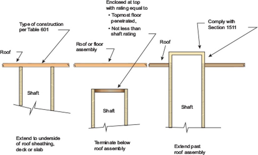
- The top of shaft enclosures shall comply with one of the following:
- Extend to the underside of the roof sheathing, deck or slab of the building, and the roof assembly shall comply with the requirements for the type of construction as specified in Table 601.
- Terminate below the roof assembly and be enclosed at the top with construction of the same fire-resistance rating as the topmost floor penetrated by the shaft, but not less than the fire-resistance rating required for the shaft enclosure.
- Extend past the roof assembly and comply with the requirements of Section 1511. IBC 713.12
- Waste, recycling and linen chutes shall comply with the provisions of NFPA 82, Chapter 6 and shall meet the requirements of Sections 712 and 713.13.1 through 713.13.6. Incinerator rooms shall meet the provisions of Sections 713.13.4 and 713.13.5. Exception: Chutes serving and contained within a single dwelling unit. IBC 713.13
- A shaft enclosure containing a recycling, waste or linen chute shall not be used for any other purpose and shall be enclosed in accordance with Section 713.4. A shaft enclosure shall be permitted to contain recycling and waste chutes. Openings into the shaft, from access rooms and discharge rooms, shall be protected in accordance with this section and Section 716. Openings into chutes shall not be located in corridors. Doors into chutes shall be self-closing. Discharge doors shall be self-or automatic-closing upon the actuation of a smoke detector in accordance with Section 716.2.6.6, except that heat-activated closing devices shall be permitted between the shaft and the discharge room. IBC 713.13.1
- Access openings for waste, recycling or linen chutes shall be located in rooms or compartments enclosed by not less than 1-hour fire barriers constructed in accordance with Section 707 or horizontal assemblies constructed in accordance with Section 711, or both. Openings into the access rooms shall be protected by opening protectives having a fire protection rating of not less than 3/4 hour. Doors shall be self- or automatic closing upon the detection of smoke in accordance with Section 716.2.6.6. The room or compartment shall be configured to allow the access door to the room or compartment to close and latch with the access panel to the chute in any position. IBC 713.13.3
- Table 509.1Waste, recycling or linen chutes shall discharge into an enclosed room separated by fire barriers with a fire-resistance rating not less than the required fire rating of the shaft enclosure and constructed in accordance with Section 707 or horizontal assemblies constructed in accordance with Section 711, or both. Openings into the discharge room from the remainder of the building shall be protected by opening protectives having a fire protection rating equal to the protection required for the shaft enclosure. Doors shall be self- or automatic closing upon the detection of smoke in accordance with Section 716.2.6.6. Waste chutes shall not terminate in an incinerator room. Waste and linen rooms that are not provided with chutes need only comply with Table 509.1. IBC 713.13.4
- Elevator, dumbwaiter and other hoistway enclosures shall be constructed in accordance with Sections 712 and 713, and Chapter 30. IBC 713.14
Penetrations (714)
- Penetrations of fire-resistance-rated walls by ducts that are not protected with dampers shall comply with Sections 714.3 through 714.4.3. Penetrations of horizontal assemblies not protected with a shaft as permitted by Section 717.6, and not required to be protected with fire dampers by other sections of this code, shall comply with Sections 714.5 through 714.6.2. Ducts and air transfer openings that are protected with dampers shall comply with Section 717. IBC 714.1.1
- Penetrations into or through fire walls, fire barriers, smoke barrier walls and fire partitions shall comply with Sections 714.4.1 through 714.4.3. Penetrations in smoke barrier walls shall also comply with Section 714.5.4. IBC 714.4
- Through penetrations of fire-resistance-rated walls shall comply with Section 714.4.1.1 or 714.4.1.2.
Exception: Where the penetrating items are steel, ferrous or copper pipes, tubes or conduits, the annular space between the penetrating item and the fire-resistance-rated wall is permitted to be protected by either of the following measures: IBC 714.4.1- In concrete or masonry walls where the penetrating item is a maximum 6-inch (152 mm) nominal diameter and the area of the opening through the wall does not exceed 144 square inches (0.0929 m2), concrete, grout or mortar is permitted where installed the full thickness of the wall or the thickness required to maintain the fire-resistance rating.
- The material used to fill the annular space shall prevent the passage of flame and hot gases sufficient to ignite cotton waste when subjected to ASTM E119 or UL 263 time-temperature fire conditions under a minimum positive pressure differential of 0.01 inch (2.49 Pa) of water at the location of the penetration for the time period equivalent to the fire-resistance rating of the construction penetrated.
- Through penetrations shall be protected by an approved penetration firestop system installed as tested in accordance with ASTM E814 or UL 1479, with a minimum positive pressure differential of 0.01 inch (2.49 Pa) of water and shall have an F rating of not less than the required fire-resistance rating of the wall penetrated. IBC 714.4.1.2
- Membrane penetrations shall comply with Section 714.4.1. Where walls or partitions are required to have a fire-resistance rating, recessed fixtures shall be installed such that the required fire resistance will not be reduced. (exceptions apply) IBC 714.4.2
- Electrical outlet boxes located on opposite sides of fire-resistance rated walls must be separated by a horizontal distance of 24 in. IBC 714.4.2 exception 1.1
- Recessed light fixtures in fire-resistance rated ceilings must be protected or be listed for use in a fire-resistance rated assembly. IBC 714.5.2
Fire-Resistant Joints (715)
- Provide approved assembly numbers for all fire-resistant joint systems. The provisions of IBC 715.1 shall govern the materials and methods of construction used to protect joints and voids in or between horizontal and vertical assemblies. IBC 715.1
- Joints installed in or between fire-resistance-rated walls, floor or floor/ceiling assemblies and roofs or roof/ceiling assemblies shall be protected by an approved fire-resistant joint system designed to resist the passage of fire for a time period not less than the required fire-resistance rating of the wall, floor or roof in or between which the system is installed. IBC 715.3
- Fire-resistant joint systems shall be tested in accordance with the requirements of either ASTM E1966 or UL 2079. Nonsymmetrical wall joint systems shall be tested with both faces exposed to the furnace, and the assigned fire-resistance rating shall be the shortest duration obtained from the two tests. Where evidence is furnished to show that the wall was tested with the least fire-resistant side exposed to the furnace, subject to acceptance of the building official, the wall need not be subjected to tests from the opposite side. Exception: For exterior walls with a horizontal fire separation distance greater than 10 feet (3048 mm), the joint system shall be required to be tested for interior fire exposure only. IBC 715.3.1
- Voids created at the intersection of exterior curtain wall assemblies and fire-resistance-rated floor, or floor/ceiling assemblies shall be protected with an approved perimeter fire containment system to prevent the interior spread of fire. Such systems shall provide an F rating for a time period not less than the fire-resistance rating of the floor or floor/ceiling assembly. IBC 715.4
Opening Protectives (716)
- Opening protectives required by other sections of this code shall comply with the provisions of this section and shall be installed in accordance with NFPA 80. IBC 716.1
- Glazing used in fire door assemblies and fire window assemblies shall comply with this section in addition to the requirements of Sections 716.2 and 716.3, respectively. IBC 716.1.2
- Fire door assemblies in interior exit stairways and ramps and exit passageways shall have a maximum transmitted temperature rise of not more than 450°F above ambient at the end of 30 minutes of standard fire test exposure. Exception: The maximum transmitted temperature rise is not required in buildings equipped throughout with an automatic sprinkler system installed in accordance with Section 903.3.1.1 or 903.3.1.2. IBC 716.2.2.3
- Fire-protection-rated glazing in excess of 100 square inches (0.065 m2) is not permitted. Fire-resistance-rated glazing in excess of 100 square inches shall be permitted in fire doors. Listed fire-resistance-rated glazing in a fire door shall have a maximum transmitted temperature rise in accordance with Section 716.2.2.3 when the fire door is tested in accordance with NFPA 252, UL 10B or UL 10C. IBC 16.2.2.3.1
- Fire doors installed within a fire door & frames assembly shall meet the fire rating indicated in Table 716.1(2). IBC 716.2.3 & 716.2.4
- Fire-protection-rated glazing shall be prohibited in fire walls and fire barriers except as provided in Sections 716.2.5.1.2.1 and 716.2.5.1.2.2. IBC 716.2.5.1.2
- Fire-protection-rated glazing shall be permitted as vision panels in self-closing swinging fire door assemblies serving as horizontal exits in fire walls where limited to 100 square inches. IBC 716.2.5.1.2.1
- Fire-protection-rated glazing shall be permitted in fire doors having a 11/2-hour fire protection rating intended for installation in fire barriers, where limited to 100 square inches. IBC 716.5.8.1.2.2
- In a 20-minute fire door assembly (corridors & smoke barriers), the glazing material in the door itself shall have a minimum fire-protection-rated glazing of 20 minutes and shall be exempt from the hose stream test. IBC 716.2.5.3
- Fire-protection-rated glazing shall be permitted in door frames with transom lights, sidelights or both, where a 3/4-hour fire protection rating or less is required and in 2-hour fire-resistance-rated exterior walls in accordance with Table 716.1(2). Fire door frames with transom lights, sidelights or both, installed with fire-resistance-rated glazing tested as an assembly in accordance with ASTM E119 or UL 263 shall be permitted where a fire protection rating exceeding 3/4 hour is required in accordance with Table 716.1(2). IBC 716.2.5.4
- Fire door hardware and closures shall be installed on fire door assemblies in accordance with the requirements of this section. IBC 716.2.6
- Fire doors shall be latching and self- or automatic closing in accordance with this section. (exceptions apply) IBC 716.2.6.1
- Automatic-closing fire door assemblies shall be self-closing in accordance with NFPA 80. IBC 716.2.6.4
- Doors required to be self-closing and not required to be automatic closing shall be permitted to be equipped with delayed-action closers. IBC 716.2.6.5
- Automatic-closing doors installed in the following locations shall be permitted to have hold-open devices. Doors shall automatically close by the actuation of smoke detectors installed in accordance with Section 907.3 or by loss of power to the smoke detector or hold-open device. Doors that are automatic-closing by smoke detection shall not have more than a 10-second delay before the door starts to close after the smoke detector is actuated. Automatic-closing doors that protect openings installed in the following locations shall comply with this section. IBC 716.2.6.6
- In walls that separate incidental uses in accordance with Section 509.4.
- In fire walls in accordance with Section 706.8.
- In fire barriers in accordance with Section 707.6.
- In fire partitions in accordance with Section 708.6.
- In smoke barriers in accordance with Section 709.5.
- In smoke partitions in accordance with Section 710.5.2.3.
- In shaft enclosures in accordance with Section 713.7.
- In waste and linen chutes, discharge openings and access and discharge rooms in accordance with Section 713.13. Loading doors installed in waste and linen chutes shall meet the requirements of Sections 716.2.6.1 and 716.2.6.3.
- Vertical sliding or vertical rolling steel fire doors in openings through which pedestrians travel shall be heat activated or activated by smoke detectors with alarm verification. IBC 716.2.6.7
- Where fire shutters of the swinging type are installed in exterior openings, not less than one row in every three vertical rows shall be arranged to be readily opened from the outside and shall be identified by distinguishing marks or letters not less than 6 inches high. IBC 716.2.7
- Where fire shutters of the rolling type are installed, such shutters shall include approved automatic-closing devices. IBC 716.2.8
- Installation of smoke doors shall be in accordance with NFPA 105. IBC 716.2.10
- Fire-protection-rated glazing used in fire window assemblies located in fire partitions and fire barriers shall be limited to use in assemblies with a maximum fire-resistance rating of 1 hour in accordance with this section. IBC 716.3.2.1
- Fire-protection-rated glazing requiring 45-minute opening protection in accordance with Table 716.1(3) shall be limited to fire partitions designed in accordance with Section 708 and fire barriers utilized in the applications set forth in Sections 707.3.6, 707.3.7 and 707.3.9 where the fire-resistance rating does not exceed 1 hour. Fire-resistance-rated glazing assemblies tested in accordance with ASTM E119 or UL 263 shall not be subject to the limitations of this section. IBC 716.3.2.1.1
- The total area of the glazing in fire-protection-rated window assemblies shall not exceed 25 percent of the area of a common wall with any room. IBC 716.3.2.1.2
- Fire window frames installed with a fire window assembly shall meet the fire-protection rating indicated in Table 716.1(3).
- Glazing in fire window assemblies shall be fire protection rated in accordance with this section and Table 716.1(3). Fire-protection-rated glazing in fire window assemblies shall be tested in accordance with and shall meet the acceptance criteria of NFPA 257 or UL 9. Openings in nonfire-resistance-rated exterior wall assemblies that require protection in accordance with Section 705.3, 705.8, 705.8.5 or 705.8.6 shall have a fire protection rating of not less than 3/4 hour. Fire-protection-rated glazing in 1/2-hour fire-resistance-rated partitions is permitted to have a 20-minute fire protection rating. IBC 716.3.4
- Glazing in fire window assemblies shall be fire-protection-rated glazing installed in accordance with and complying with the size limitations set forth in NFPA 80.
- Fire-protection-rated glazing shall be in the fixed position or be automatic-closing and shall be installed in labeled frames. IBC 716.3.6.1
- Fire protective curtain assemblies used to protect openings where smoke and draft control assemblies are required shall comply with Section 716.2.1.4. IBC 716.4.2
Ducts & Air Transfer Openings (717)
- Ducts transitioning horizontally between shafts shall not require a shaft enclosure provided that the duct penetration into each associated shaft is protected with dampers complying with this section. IBC 717.1.1
- The space around a duct penetrating a nonfire-resistance-rated floor assembly shall comply with Section 717.6.3. IBC 717.1.2.1
- Fire dampers for hazardous exhaust duct systems shall comply with the International Mechanical Code. IBC 717.2.2
- Fire dampers shall have the minimum rating specified in Table 717.3.2.1. IBC 717.3.2.1
- Combination fire/smoke dampers shall have the minimum rating specified for fire dampers in Table 717.3.2.1 and shall have the minimum rating specified for smoke dampers in Section 717.3.2.2. IBC 717.3.2.3
- Damper actuation shall be in accordance with Sections 717.3.3.1 through 717.3.3.5 as applicable. IBC 717.3.3
- Fire and smoke dampers shall be provided with an approved means of access that is large enough to permit inspection and maintenance of the damper and its operating parts. Dampers equipped with fusible links, internal operators, or both shall be provided with an access door that is not less than 12 inches (305 mm) square or provided with a removable duct section. IBC 717.4.1
- Access points shall be permanently identified on the exterior by a label having letters not less than 1/2 inch (12.7 mm) in height reading: "FIRE/SMOKE DAMPER," "SMOKE DAMPER" or "FIRE DAMPER." IBC 717.4.2
- Ducts and air transfer openings permitted in fire walls in accordance with Section 706.11 shall be protected with listed fire dampers installed in accordance with their listing. IBC 717.5.1
- A listed smoke damper designed to resist the passage of smoke shall be provided at each point a duct or air transfer opening penetrates a fire wall that serves as a horizontal exit. IBC 717.5.1.1
- Ducts and air transfer openings of fire barriers shall be protected with listed fire dampers installed in accordance with their listing. Ducts and air transfer openings shall not penetrate enclosures for interior exit stairways and ramps and exit passageways, except as permitted by Sections 1023.5 and 1024.6, respectively. (exceptions apply) IBC 717.5.2
- A listed smoke damper designed to resist the passage of smoke shall be provided at each point a duct or air transfer opening penetrates a fire barrier that serves as a horizontal exit. IBC 717.5.2.1
- Shaft enclosures that are permitted to be penetrated by ducts and air transfer openings shall be protected with listed fire and smoke dampers installed in accordance with their listing. (exceptions apply) IBC 717.5.3
- Ducts and air transfer openings that penetrate fire partitions shall be protected with listed fire dampers installed in accordance with their listing. (exceptions apply) IBC 717.5.4
- Duct and air transfer openings that penetrate corridors shall be protected with dampers as follows:
- A corridor damper shall be provided where corridor ceilings, constructed as required for the corridor walls as permitted in Section 708.4, Exception 3, are penetrated.
- A ceiling radiation damper shall be provided where the ceiling membrane of a fire-resistance-rated floor-ceiling or roof-ceiling assembly, constructed as permitted in Section 708.4, Exception 2, is penetrated.
- A listed smoke damper designed to resist the passage of smoke shall be provided at each point a duct or air transfer opening penetrates a corridor enclosure required to have smoke and draft control doors in accordance with Section 716.2.2.1. (see exceptions) IBC 717.5.4.1
- A listed smoke damper designed to resist the passage of smoke shall be provided at each point a duct or air transfer opening penetrates a smoke barrier. Smoke dampers and smoke damper actuation methods shall comply with Section 717.3.3.2. (exceptions apply) IBC 717.5.5
- A listed smoke damper designed to resist the passage of smoke shall be provided at each point that an air transfer opening penetrates a smoke partition. Smoke dampers and smoke damper actuation methods shall comply with Section 717.3.3.2. Exception: Where the installation of a smoke damper will interfere with the operation of a required smoke control system in accordance with Section 909, approved alternative protection shall be utilized. IBC 717.5.7
- Penetrations by ducts and air transfer openings of a floor, floor/ceiling assembly or the ceiling membrane of a roof/ceiling assembly shall be protected by a shaft enclosure that complies with Section 713 or shall comply with Sections 717.6.1 through 717.6.3. IBC 717.6
- In occupancies other than Groups I-2 and I-3, a duct constructed of approved materials in accordance with the International Mechanical Code that penetrates a fire-resistance-rated floor/ceiling assembly that connects not more than two stories is permitted without shaft enclosure protection, provided that a listed fire damper is installed at the floor line or the duct is protected in accordance with Section 714.5. For air transfer openings, see Section 712.1.9. (see exceptions) IBC 717.6.1
- Ducts and air transfer openings constructed of approved materials in accordance with the International Mechanical Code that penetrate the ceiling membrane of a fire-resistance-rated floor/ceiling or roof/ceiling assembly shall be protected with one of the following:
- A shaft enclosure in accordance with Section 713.
- A listed ceiling radiation damper installed at the ceiling line where a duct penetrates the ceiling of a fire-resistance-rated floor/ceiling or roof/ceiling assembly.
- A listed ceiling radiation damper installed at the ceiling line where a diffuser with no duct attached penetrates the ceiling of a fire-resistance-rated floor/ceiling or roof/ceiling assembly.
(see exceptions) IBC 717.6.2.1
- Duct systems constructed of approved materials in accordance with the International Mechanical Code that penetrate nonfire-resistance-rated floor assemblies shall be protected by any of the following methods:
- A shaft enclosure in accordance with Section 713.
- The duct connects not more than two stories, and the annular space around the penetrating duct is protected with an approved noncombustible material that resists the free passage of flame and the products of combustion.
- In floor assemblies composed of noncombustible materials, a shaft shall not be required where the duct connects not more than three stories, the annular space around the penetrating duct is protected with an approved noncombustible material that resists the free passage of flame and the products of combustion, and a fire damper is installed at each floor line.
Exception: Fire dampers are not required in ducts within individual residential dwelling units. IBC 717.6.3
Concealed Spaces (718)
- In combustible construction, fireblocking shall be installed to cut off concealed draft openings (both vertical and horizontal) and shall form an effective barrier between floors, between a top story and a roof or attic space. Fireblocking shall be installed in the locations specified in sec. 718.2.2- 718.2.7. Provide details on plans, or complete notes on the drawings. IBC 718.2
- Provide draftstopping details. Draftstopping shall be installed to subdivide floor/ceiling assemblies where required by Section 708.4.2. In other than Group R occupancies, draftstopping shall be installed to subdivide combustible floor/ceiling assemblies so that horizontal floor areas do not exceed 1,000 square feet.
Exception: Buildings equipped throughout with an automatic sprinkler system in accordance with Section 903.3.1.1. IBC 718.3 - Provide draft stops to subdivide attic spaces and concealed roof spaces such that any horizontal area does not exceed 3,000 square feet. IBC 718.4, 708.4.2
Exception: Buildings equipped throughout with an automatic sprinkler system in accordance with Section 903.3.1.1. - Provide an attic draft-stopping plan showing compliance with IBC 718.3 and 718.4
- Fire-blocking must be installed in combustible construction to cut off vertical and horizontal concealed draft openings and must form an effective barrier between floors, between a top story and a roof or attic. IBC 718.2 and 718.2.1
- Draft-stopping must be installed in floors and attics in buildings of combustible construction buildings. IBC 718.3 and 718.4 (see exceptions)
Interior Finishes (Chapter 8)
- Interior wall and ceiling finish shall be in accordance with Table 803.13.
- Interior wall and ceiling finish shall have a flame spread index not greater than that specified in Table 803.13 for the group and location designated. Interior wall and ceiling finish materials tested in accordance with NFPA 286 and meeting the acceptance criteria of Section 803.1.1.1, shall be permitted to be used where a Class A classification in accordance with ASTM E84 or UL 723 is required. IBC 803.13
- An interior wall or ceiling finish material that is not more than 1/4 inch thick shall be applied directly onto the wall, ceiling or structural element without the use of furring strips and shall not be suspended away from the building element to which that finish material it is applied. (exceptions apply) IBC 803.15.4
- Interior floor finish and floor covering materials shall comply with Sections 804.2 through 804.4.2. (exceptions apply) IBC 804.1
- Combustible materials installed on or embedded in floors of buildings of Type I or II construction shall comply with Sections 805.1.1 through 805.1.3 (exceptions apply). IBC 805.1
- The following requirements shall apply to all occupancies: IBC 806.1
- Furnishings or decorative materials of an explosive or highly flammable character shall not be used.
- Fire-retardant coatings in existing buildings shall be maintained so as to retain the effectiveness of the treatment under service conditions encountered in actual use
- Furnishings or other objects shall not be placed to obstruct exits, access thereto, egress therefrom or visibility thereof.
- The permissible amount of decorative vegetation and noncombustible decorative materials shall not be limited.
- In Groups A, B, E, I, M and R-1 and in dormitories in Group R-2, curtains, draperies, fabric hangings and similar combustible decorative materials suspended from walls or ceilings shall comply with Section 806.4 and shall not exceed 10 percent of the specific wall or ceiling area to which such materials are attached. Fixed or movable walls and partitions, paneling, wall pads and crash pads applied structurally or for decoration, acoustical correction, surface insulation or other purposes shall be considered to be interior finish, shall comply with Section 803 and shall not be considered to be decorative materials or furnishings. (exceptions apply) IBC 806.2
- Foam plastic used as trim in any occupancy shall comply with Section 2604.2. IBC 806.5
- Where lockers constructed of combustible materials are used, the lockers shall be considered to be interior finish and shall comply with Section 803. Exception: Lockers constructed entirely of wood and noncombustible materials shall be permitted to be used wherever interior finish materials are required to meet a Class C classification in accordance with Section 803.1.2. IBC 806.9
- Thermal and acoustical insulation shall comply with Section 720. IBC 807.1
- Foam plastic insulation shall comply with Section 2603.1. Except as provided for in Sections 2603.4.1 and 2603.9, foam plastic shall be separated from the interior of a building by an approved thermal barrier of 1/2-inch gypsum wallboard, heavy timber in accordance with Section 602.4 or a material that is tested in accordance with and meets the acceptance criteria of both the Temperature Transmission Fire Test and the Integrity Fire Test of NFPA 275. Combustible concealed spaces shall comply with Section 718.
A barrier is mandated to provide a minimum degree of protection between foam plastic materials and a building’s occupants. Any type of separation equivalent to that provided by ½-inch gypsum board is considered acceptable. See notes from commentary - Acoustical materials complying with the interior finish requirements of Section 803 shall be installed in accordance with the manufacturer's recommendations and applicable provisions for applying interior finish. IBC 808.1.1
- Acoustical ceiling systems that are part of fire-resistance-rated construction shall be installed in the same manner used in the assembly tested and shall comply with the provisions of Chapter 7. IBC 808.1.1.2
Fire Protection (Chapter 9)
- Approved automatic sprinkler systems in new buildings and structures shall be provided in the locations described in Sections 903.2.1 through 903.2.12. IBC 903.2
- Persons shall not remove or modify any fire protection system installed or maintained under the provisions of this code or the International Fire Code without approval by the building official. IBC 901.3
- Where buildings, or portions thereof, are divided into fire areas so as not to exceed the limits established for requiring a fire protection system in accordance with this chapter, such fire areas shall be separated by fire walls constructed in accordance with Section 706, fire barriers constructed in accordance with Section 707, or horizontal assemblies constructed in accordance with Section 711, or a combination thereof having a fire-resistance rating of not less than that determined in accordance with Section 707.3.10. IBC 901.7
- Automatic sprinkler systems required during construction, alteration and demolition operations shall be provided in accordance with Section 3314. IBC 903.2.12
- Portable fire extinguishers shall be installed in accordance with IBC Section 906. IBC 906.1
Fire Sprinkler System Design Intent
The 2019 edition of NFPA 13, 13R, and 13D are the principal reference standard
- Tennessee registrant’s design concept shall specify the system type, its capabilities, and operational criteria sufficient for development of the fire sprinkler contractor’s detailed shop drawings. All documents shall be sealed by a Tennessee registrant. Rule 0780-02-03-.03, 0780-02-03-.03(b), Rule 0120-02-.08(3)
- Shop drawings shall be based upon the designing engineer’s design intent. The shop drawings will be a stipulation on the plans upon initial approval of the project.
- Shop drawings must be approved by the TN registrant that produced the design intent prior to submission to the State Fire Marshal’s Office.
- Shop drawings shall provide details from the point of service. Point of service is defined as the point immediately after the tap of the service main where water is used exclusively for fire protection purposes. Rule 0780-02-07-.01(g)
- Engineer sealed fire sprinkler shop drawings will not be accepted as an engineer’s design intent unless accompanied with a signed and sealed letter stating that the licensed “Responsible Managing Employee” who prepared the drawings is either:
- A Tennessee registrant in accordance with the Architects and Engineers Licensing Law Rules, or
- Under the responsible charge of the Tennessee registrant who is a staff employee of the sprinkler company.
In such a case, the drawings may be accepted as both the design intent and sprinkler shop drawing submittal.
Information to be Provided on the Plan Set Cover Sheet
- Identify the specific sprinkler standard to be used in the design drawings and scope of building protection: e.g., Equipped Throughout, Partial, Incidental Area. IBC 107.2.1, IBC 903.3.1
- The Sprinkler Design Intent drawings shall be indexed on the Cover Sheet of the plan set. IBC 107.2.1 & 2.
- Identify the standpipe Class in accordance with IBC 905.
- Where storage use and occupancy are identified, provide details for protection of special storage and commodities in accordance with NFPA 13 Chapter 20.
- State if seismic protection is required based on Seismic Design Category. Seismic protection shall be in accordance with NFPA 13, Chapter 18.
Note: Fire sprinkler component importance factor 1.5 per ASCE 7.13.1.3. If Seismic Design Category is C, D, E, or F, seismic design criteria is required.
Water Supply Availability and System Demand
- Specify the type of water supply provided to supply the required fire flow. IFC 507.2
- Where meters are required by other authorities, they shall be listed. NFPA 13, 23.1.7
- Provide flow test information:
- Name of person who conducted the flow test.
- Date and location of test.
Note: The test must be less than six months old. If reliable or current information is not available, the engineer should supervise the performance of a new flow test and/or will verify the accuracy of a new flow test during preliminary design. A&E Board Standard of Care for fire sprinkler design. IFC 507.1, NFPA 13 4.6 Water supply information.
- Provide preliminary hydraulic calculation results including, required design density, area of application, required hose stream, and required duration. IBC (IFC) 903.3.8.5 Calculations.
- Where the potential exists for water pressures exceeding 175 psi, provide a pressure reducing valve meeting the requirements of NFPA 13.16.9.1.2. Specify the setting for pressure-reducing valves.
- Identify the sprinkler system occupancy hazard classification for the facility or portion of the facility, as follows: Light and Ordinary (Groups 1 and 2), Extra (Groups 1 and 2), or Special Occupancy Hazards (See Ch. 26). NFPA 13 4.3 & Chapter 19.3.1.2.4
Note: Commercial kitchens, Storage spaces 50 sf or larger, janitor closets, and gas furnace rooms must be Ordinary Group 1. Large stack rooms in Libraries and Stage Areas must be Ordinary Group 2. Laboratories using chemicals must be classified Ordinary Group 1 (Class C or D laboratory) or Ordinary Group 2 (Class A or B laboratory). NFPA 45 6.1.1.1 - Provide the following calculations based on NFPA 13 Chapter 19, NFPA 13R Chapter 7, or NFPA 13D Chapter 10:
- Identify the hydraulically most demanding area of the building. NFPA 13 19.3.3.1.1
- Provide preliminary flow (GPM) and pressure (SPI) demand calculations for the greatest demand area. Include the required sprinkler head pressure, sprinkler system piping elevation loss, and friction loss (including device friction loss such as backflow preventers and isolation valves). NFPA 13 Chapter 19.3.2;19.3.2.6.2, & IFC Commentary Figure 903.3.1
- NFPA 13: Density/Area Concept, duration is based upon occupancy hazard. 19.3.3.1.1
- NFPA 13R: 4-Head design, 30-minute duration
- NFPA 13D: 2-Head design, 10-minute duration
- Provide a graph plotting the water supply curve (static psi at zero GPM flow and residual psi at GPM flow) and system demand (preliminary calculated point of residual psi at GPM flow) to show that the water supply (fire hydrant test) exceeds sprinkler system water demand for the building. NFPA13.19.3.3
Civil Utility Plan Requirements
- Civil Drawings shall include the following items that pertain to the design of the private fire service main (IFC 507.2.1 Types of water supply and NFPA 24 4.1.3 Plans): See item 12.
- Size and location of all water supplies and underground utilities.
- The following items that pertain to private fire service mains:
- Size, length, location, material
- Point of connection to the main
- Sprinkler systems point of service. Point of service means the point immediately after the tap of the service main where water is used exclusively for fire protection purposes.
- Sizes, types, and locations of valves, valve indicators, regulators, meters, and valve pits.
- Depth at which the top of the pipe is laid below grade.
- Method of restraint
- The following items that pertain to hydrants:
- Size, location, number of outlets, and whether outlets are to be equipped with independent gate valves.
- Static and residual hydrants used in flow
- Method of restraint
- Size, location, and piping arrangement of fire department connections
- All connections to private fire service mains for fire protection systems shall be arranged in accordance with one of the following so that they can be isolated (IFC 507.2.1 and NFPA 24 6.2.9):
- A post indicator valve installed not less than 40 ft. from the building. For buildings less than 40 ft. in height, a post indicator valve shall be permitted to be installed closer than 40 ft. but at least as far from the building as the height of the wall facing the post indicator valve.
- A wall post indicator valve.
- An indicating valve in a pit, installed in accordance with Section 6.4.
- A backflow preventer with at least one indicating valve not less than 40 ft. from the building. For buildings less than 40 ft. in height, a backflow preventer with at least one indicating valve shall be permitted to be installed closer than 40 ft. but at least as far from the building as the height of the wall facing the backflow preventer.
- A non-indicating valve, such as an underground gate valve with an approved roadway box, complete with T-wrench, located not less than 40 ft. from the building. For buildings less than 40 ft. in height, a non-indicating valve shall be permitted to be installed closer than 40 ft. but at least as far from the building as the height of the wall facing the backflow preventer.
- Control valves installed in a fire-rated room accessible from the exterior.
- Control valves in a fire-rated stair enclosure accessible from the exterior.
Automatic Sprinkler System Design Intent Site Plan (Underground)
- Provide the following information on the Automatic Sprinkler System Design Intent site plan:
- Show the location of the point of service for the underground sprinkler piping on the site plan. and provide a note stating, “Installation of all sprinkler system piping from the point of service must be performed by a Tennessee registered sprinkler contractor.” Rule 0780-2-7-.08
- Provide details of the underground piping from the point of service to the building. Identify: the NFPA 24 6.1 system isolation valve location & type, underground piping material type and size, depth of bury,
- valve pit, trench detail, and thrust block size and location. IFC 507.2.1, NFPA 24 Chapter 4, 5, 10, and NFPA 13 Chapter 6, NFPA 13R 5.3, NFPA 13D
- The potable water supply shall be protected against backflow in accordance with the requirements of this section and the International Plumbing Code. IBC 903.3.5, IPC 608.2
- Identify whether a reduced pressure backflow preventer or meter are present. When used, specify that this equipment is listed for fire protection use. NFPA 24 5.3
- With respect to hydrants, driveways, buildings and landscaping, and fire department connections shall be so located that fire apparatus and hose connected to supply the system will not obstruct access to the buildings for other fire apparatus.
- Visible location: Fire department connections shall be located on the street side of buildings, fully visible and recognizable from the street or nearest point of fire department vehicle access or as otherwise approved by the fire chief. IBC 912.2.1
- Existing buildings: On existing buildings, wherever the fire department connection is not visible to approaching fire apparatus, the fire department connection shall be indicated by an approved sign mounted on the street front or on the side of the building. IFC 912.2.2
- Show the location of the fire pump and/or water tank location when required by design. NFPA 24 5.6, and 5.7
- Valves controlling the water supply for automatic sprinkler systems, pumps, tanks, water levels and temperatures, critical air pressures and waterflow switches on all sprinkler systems shall be electrically supervised by a listed fire alarm control unit.
Exceptions:- Automatic sprinkler systems protecting one- and two-family dwellings.
- Limited area sprinkler systems in accordance with Section 903.3.8.
- Automatic sprinkler systems installed in accordance with NFPA 13R where a common supply main is used to supply both domestic water and the automatic sprinkler system, and a separate shutoff valve for the automatic sprinkler system is not provided.
- Jockey pump control valves that are sealed or locked in the open position.
- Control valves to commercial kitchen hoods, paint spray booths or dip tanks that are sealed or locked in the open position.
- Valves controlling the fuel supply to fire pump engines that are sealed or locked in the open position.
- Trim valves to pressure switches in dry, preaction and deluge sprinkler systems that are sealed or locked in the open position.
- Underground key or hub gate valves in roadway boxes.
- Service mains must not run under buildings unless special precautions are taken. Provide details showing the method utilized, e.g., arched foundation walls, covered trenching, and isolation valves. NFPA 13 5.1.6.2
- Provide a lead-in detail where the underground piping passes through the foundation and attaches to the riser. Clearance shall be provided around all piping extending through walls, floors, platforms, and foundations, including drains, fire department connections, and other auxiliary piping. NFPA 13 6.4.3.1
General Automatic Sprinkler Design Intent
- Provide details of the system as applicable:
- Total area protected on each floor. IFC Figure 903.3
- Pipe type and schedule of wall thickness. NFPA 13 Ch. 27.5; IFC Figure 903.3
- Type and nominal K-factor of sprinklers. NFPA 13 7.2.2; IFC Figure 903.3
- Calculation of loads for sizing, details of sway bracing NFPA 13 18.5.8; See item 9.
- Temperature rating of any high-temperature sprinklers NFPA 13 8.9.6; IFC Figure 903.3
- Give the size and location of all risers and mains. NFPA 13 27.5.1.4, & 5.1.3; IFC Figure 903.3
- Give the location of any small enclosures in which no sprinklers are to be installed. IFC 903.3.1.1.1 Exempt locations.
- Give the location of any areas where sprinklers are omitted by exceptions of NFPA 13 or 13-R.
See NFPA 13 4.5 for area limitations. - Location of pre-action or deluge valves. NFPA 13 8.3; IFC Figure 903.3
- Size and location of standpipe riser and hose outlets NFPA 14 7.6 & 12.6: IFC Figure 903.3
- Specify that all system gauges and valves must be accessible for operation, inspection, tests, and maintenance. NFPA 13 16.1.1 901.4.6 Pump & riser room size. Show clearance at equipment. Such as in a dotted line.
- Where automatic sprinkler systems are required by this code, quick-response or residential automatic sprinklers shall be installed in the following areas in accordance with Section IBC (IFC) 903.3.1 and their listings in accordance with IBC (IFC) 903.3.2:
- Throughout all spaces within a smoke compartment containing care recipient sleeping units in Group I-2 in accordance with the International Building Code.
- Throughout all spaces within a smoke compartment containing gas fireplace appliances and decorative gas appliances in Group I-2 in accordance with the International Building Code.
- Throughout all spaces within a smoke compartment containing treatment rooms in ambulatory care facilities.
- Dwelling units and sleeping units in Group I-1 and R occupancies.
- Light-hazard occupancies as defined in NFPA 13.
- Automatic sprinklers shall be installed with due regard to obstructions that will delay activation or obstruct the water distribution pattern. Automatic sprinklers shall be installed in or under covered kiosks, displays, booths, concession stands, or equipment that exceeds 4 feet in width. Not less than a 3-foot clearance shall be maintained between automatic sprinklers and the top of piles of combustible fibers. IBC (IFC) 903.3.3
- Show that the automatic sprinkler system is supervised per IBC 901.6.1 & 903.4 See exceptions
- Provide tamper switches at all control valves.
- Provide a flow switch or alarm check valve and specify connection to the general building alarm that sounds within 5 minutes of flow. NFPA 13 7.7
- For high-rise buildings, the requirements of NFPA 13 16.11.10 must be met.
- Identify the type of above ground pipe or tube materials used for the sprinkler system.
NFPA 13 7.3, NFPA 13R 5.2, NFPA 13D 5.2; IFC Figure 903.3 - All sprinkler pipe and fittings shall be so installed that the system can be drained. NFPA 13 16.10.1 & 16.12.7, NFPA 13R 6.9.1, NFPA 13D 7.2.1. Provide a method for drainage where the lead-in terminates at a point lower than grade.
- Show location of the test connection(s). Test connections shall be provided at locations that will permit flow tests of water supplies and connections. NFPA 13 16.10.4.6, NFPA 13R 6.10.1, NFPA13D 7.2.4.
- Specify seismic restraints for sprinkler piping and specify flexible couplings at flexure joints per NFPA 13 18.1 & 18.2.
- Methods of providing earthquake protection of sprinkler systems shall be based on a seismic analysis certified by a registered professional engineer such that system performance will be at least equal to that of the building structure under expected seismic forces shall be permitted. NFPA 13 18.1.2
- Flexible couplings shall be arranged to coincide with structural separations within a building. NFPA 13 18.2.2
- Systems having more flexible couplings than required by this section shall be provided with additional sway bracing as required in NFPA 18.5.5.9. 18.2.3 The flexible couplings shall be installed in accordance with NFPA 13 Sections 18.2.3.1 – 18.2.4.
- Show clearance around piping passing through concrete floors and concrete/CMU walls and foundation where required. NFPA 13 18.4,
- Sprinkler protection for elevator hoistway and machine rooms shall be in compliance with NFPA 13 Section 9.3.6.
- Automatic sprinkler system riser rooms shall be designed with adequate space for all equipment necessary for the installation, as defined by the manufacturer, with sufficient working room around the stationary equipment. Clearances around equipment to elements of permanent construction, including other installed equipment and appliances, shall be sufficient to allow inspection, service, repair, or replacement without removing such elements of permanent construction or disabling the function of a required fire-resistance-rated assembly. Automatic sprinkler system riser rooms shall be provided with a door(s) and unobstructed passageway large enough to allow removal of the largest piece of equipment. IBC 901.4.7
MP&E Requirements
- Where aboveground water-filled supply pipes, risers, system risers, or feed mains pass through open areas, cold rooms, passageways, or other areas exposed to temperatures below 40°F (4°C), the pipe shall be protected against freezing by insulating coverings, frost proof casings, listed heat tracing systems, or other reliable means capable of maintaining a minimum temperature between 40°F (4°C) and 120°F (48.9°C). NFPA 13 8.3.1.8.1, NFPA 13R 6.7.2.1
- The dry-pipe valve room must be lighted and heated, and the source of heat must be a permanently installed type. NFPA 13 8.2.5.2.2
- Automatic Sprinkler Systems, from the point of service, shall be monitored by an approved supervising station. Rule 0780-02-07-.01(g) Def, IBC 901.6.1
- On the Electrical drawings, specify the NFPA 72 compliant monitoring and signal transmission device and show the location of all supervisory and alarm components which will perform the functions required by IBC 903.4 and 903.4.1 for the automatic sprinkler system.
NFPA 13 Systems
- Where the provisions of this code require that a building or portion thereof be equipped throughout with an automatic sprinkler system in accordance with this section, sprinklers shall be installed throughout in accordance with NFPA 13 except as provided in Section 903.3.1.1.1.
Exempt Locations (IBC 903.3.1.1.1): Automatic sprinklers shall not be required in the following rooms or areas where such rooms or areas are protected with an approved automatic fire detection system in accordance with Section 907.2 that will respond to visible or invisible particles of combustion. Sprinklers shall not be omitted from any room merely because it is damp, of fire-resistance-rated construction or contains electrical equipment.- Any room where the application of water, or flame and water, constitutes a serious life or fire hazard.
- Any room or space where sprinklers are considered undesirable because of the nature of the contents, when approved by the fire code official.
- Generator and transformer rooms separated from the remainder of the building by walls and floor/ceiling or roof/ceiling assemblies having a fire-resistance rating of not less than 2 hours.
- Rooms or areas that are of noncombustible construction with wholly noncombustible contents.
- Fire service access elevator machine rooms and machinery spaces.
- Machine rooms and machinery spaces associated with occupant evacuation elevators designed in accordance with Section IBC 3008.
Multiple buildings attached by canopies, covered breezeways, common roofs, or a common wall(s) shall be permitted to be supplied by a single fire sprinkler riser. The maximum system size shall comply with NFPA 13 4.5.1. IBC 903.3.1.1, NFPA 13 4.5.4.1
- Provide the total area protected of each floor for each system riser. The maximum area limitation for the provided number of risers is: Light or ordinary hazard - 52,000 sq. ft. per riser and extra hazard - 40,000 sq. ft. per riser. NFPA 13 4.5.1
- Except as permitted by IBC 903.3.1.1.1, all areas must be protected, including:
- Elevator shafts must have sidewall spray sprinklers shall be installed at the bottom of each elevator hoist way not more than 2 ft (0.61 m) above the floor of the pit. NFPA 13 9.3.6.1
- In noncombustible stair shafts having noncombustible stairs with noncombustible or limited-combustible finishes, sprinklers shall be installed at the top of the shaft and under the first accessible landing above the bottom of the shaft. NFPA 13 9.3.4.2.1
- (Provide sprinklers under all combustible ground floors, exterior docks, and platforms (see reference for exceptions). NFPA 13 9.3.18.1
- Provide sprinklers under combustible exterior roofs or canopies exceeding 4 ft. in width (see reference for exceptions). NFPA 13 9.3.19.1
- Provide sprinklers in every aisle and tier for library stack rooms (see reference for exceptions). NFPA 13 9.3.7
- Provide sprinklers for electrical equipment rooms (see reference for exceptions). NFPA 13 9.3.20.1
- Automatic sprinklers in elevator machine rooms or at the tops of hoist ways shall be of ordinary- or intermediate temperature rating. NFPA 13 9.3.6.4
- Note: The electrical equipment room exception does not apply elevator equipment rooms.
- Provide sprinklers at stages, under the stage (if combustible construction or used for storage), and at all adjacent stage areas. NFPA 13 9.3.13.1
Note: Where proscenium opening protection is required provide a deluge system with open heads no more than 3 feet from the stage side of the opening, and at a maximum of 6 feet on center. NFPA 13 9.3.13.1 9.3.13.2 - Combustible concealed spaces must be sprinklered per NFPA 13 9.3.17.1
- Within dwelling units, bathrooms, closets, and pantries are to be sprinklered per NFPA 13 9.2.4.1 & 9.2.4.2
- Provide flow test data (static psi, residual psi and gpm, who and when test was performed) for the existing sprinkler system riser when additions to existing systems are made. NFPA 13 2019 28.2.3.4.2 The main drain test shall be conducted annually at each water-based fire protection system riser to determine whether there has been a change in the condition of water supply piping and control valves. NFPA 25-2020 13.2.5
NFPA 13R Systems
- Automatic sprinkler systems in Group R occupancies up to and including four stories in height shall be permitted to be installed throughout in accordance with NFPA 13R. IBC 903.3.1.2, NFPA 13R 1.1.
- The water supply source shall be one of the following: NFPA 13R 9.5.
- A connection to a reliable waterworks system with or without a pump, as required. NFPA 13R 9.6
- An elevated tank
- A pressure tank installed in accordance with NFPA 13 and NFPA 22
- A stored water source with an automatically operated pump
- Any type of pipe or tube acceptable under the plumbing code for underground supply pipe shall be acceptable as underground supply for the system when installed between the point of connection and the system riser. NFPA 13R 5.3
- A wet pipe system shall be used where piping is installed in areas that can be maintained reliably above 40°F (4°C). NFPA 13R 5.4.1
- Piping in areas that cannot be maintained reliably above 40°F (4°C) shall be protected by use of one of the following methods (NFPA 13R 5.4.2):
- Antifreeze system using a listed antifreeze solution in accordance with NFPA 13
- Dry pipe system
- Pre-action system
- Listed standard dry-pendent, dry-upright, or dry-sidewall sprinklers extended from pipe in heated areas.
- Heat tracing in accordance with 6.7.2.2
- Sprinkler protection shall be provided for exterior balconies, decks, and ground floor patios of dwelling units where the building is of Type V construction, provided there is a roof or deck above. Sidewall sprinklers that are used to protect such areas shall be permitted to be located such that their deflectors are within 1 inch to 6 inches below the structural members and a maximum distance of 14 inches below the deck of the exterior balconies and decks that are constructed of open wood joist construction. IBC 903.3.1.2.1, NFPA 13R 6.6.5.1
- Breezeways’ (Exterior stair/Open-ended corridor) shall be constructed and protected by one of the following options:
- Breezeway enclosures shall be constructed as fire barriers in accordance with Section 707 or horizontal assemblies in accordance with Section 711, or both. Opening protectives shall be in accordance with the requirements of Section 716 and shall be limited to those necessary for exit access to the enclosure from normally occupied spaces and for egress from the enclosure. IBC 1027.6, 1023
Note: In this approach, NFPA 13R 6.6.5 may be applied and the building and the building would be protected throughout in accordance with the IBC. - Separation from the interior of the building is not required for exterior stairways or ramps connected to open-ended corridors, when designed in accordance with IBC 1027.6, Exception 4, as follows:
- The building, including corridors, stairways, or ramps, shall be equipped throughout with an automatic sprinkler system in accordance with Section 903.3.1.2.
- The open-ended corridors comply with Section 1020.
- The open-ended corridors are connected on each end to an exterior exit stairway or ramp complying with Section 1027.
- The exterior walls and openings adjacent to the exterior exit stairway or ramp comply with Section 1023.7.
- At any location in an open-ended corridor where a change of direction exceeding 45 degrees (0.79 rad) occurs, a clear opening of not less than 35 square feet or an exterior stairway or ramp shall be provided. Where clear openings are provided, they shall be located so as to minimize the accumulation of smoke or toxic gases.
- Sprinklers shall be installed in all areas except where omission is permitted by NFPA 13R 6.6.2 through 6.6.7.
- Sprinklers shall not be required in bathrooms where the bathroom area does not exceed 55 ft².
- Except where specified in 6.6.4, sprinklers shall not be required in clothes closets, linen closets, and pantries within dwelling units that meet all the following conditions:
- The area of the space does not exceed 24 ft²
- The walls and ceilings are surfaced with noncombustible or limited-combustible materials.
- Sprinklers shall be installed in any closet used for heating and air-conditioning equipment except when fuel-fired equipment is present, at least one quick-response intermediate temperature sprinkler shall be installed above the equipment.
- Sprinklers shall not be required in any porches, balconies, corridors, carports, and stairs that are open and attached, unless required by IBC 903.3.1.2.1 (exterior balconies, decks, and ground floor patios of dwelling units where the building is of Type V construction) or Breezeways designed using IBC 1027.2.
- Sprinklers shall not be required in attics, penthouse equipment rooms, elevator machine rooms, concealed spaces dedicated exclusively to and containing only dwelling unit ventilation equipment, crawl spaces, floor/ceiling spaces, noncombustible elevator shafts where the elevator cars comply with ASME A17.1, Safety Code for Elevators and Escalators, and other concealed spaces that are not used or intended for living purposes or storage and do not contain fuel-fired equipment.
- Sprinklers shall not be required in closets (regardless of size) on exterior balconies and exterior breezeways/corridors, regardless of size, as long as the closet does not have doors or unprotected penetrations directly into the dwelling unit.
- Piping hanging and bracing methods shall comply with NFPA 13. NFPA 13R 6.13
- Breezeway enclosures shall be constructed as fire barriers in accordance with Section 707 or horizontal assemblies in accordance with Section 711, or both. Opening protectives shall be in accordance with the requirements of Section 716 and shall be limited to those necessary for exit access to the enclosure from normally occupied spaces and for egress from the enclosure. IBC 1027.6, 1023
NFPA 13D Systems
- Automatic sprinkler systems installed in Group R-3 or R-4 Congregate residences with 16 or fewer residents and Group R-3 Care facilities with 5 or fewer residents (excluding staff) shall be permitted to be installed throughout in accordance with NFPA 13D. IBC 903.3.1.3, 903.2.8.1, 903.2.8.2
- The following water supply sources shall be acceptable by this standard. (NFPA 13D 6.2):
- A connection to a reliable waterworks system with or without an automatically operated pump.
- An elevated tank.
- A pressure tank designed to American Society of Mechanical Engineers (ASME) standards for a pressure vessel with a reliable pressure source.
- A stored water source with an automatically operated pump; or
- A well with a pump of sufficient capacity and pressure to meet the sprinkler system demand.
- Any type of pipe or tube acceptable under the plumbing code for underground supply pipe shall be acceptable as underground supply for the system when installed between the point of connection and the system riser. NFPA 13D 5.3
- Where system piping is located in areas not maintained above 40°F (4°C), the pipe shall be protected against freezing by use of one of the following methods:
- Dry pipe system and pre-action systems in accordance with NFPA 13D 9.3.4.
- Antifreeze system in accordance with NFPA 13D 9.2.3.
- Listed standard dry-pendent or dry-sidewall sprinklers extended from pipe in heated areas into unheated areas not intended for living purposes.
- Sprinklers shall be installed in all areas except where omission is permitted by NFPA 13D 8.3.1 through 8.3.8.
- Sprinklers shall not be required in bathrooms of 55 ft² and less.
- Sprinklers shall not be required in clothes closets, linen closets, and pantries that meet all the following conditions:
- The area of the space does not exceed 24 ft².
- The least dimension does not exceed 3 ft.
- The walls and ceilings are surfaced with noncombustible or limited-combustible materials.
- Sprinklers shall not be required in garages, open attached porches, carports, and similar structures.
- Sprinklers shall not be required in attics, penthouse equipment rooms, elevator machine rooms, concealed spaces dedicated exclusively to and containing only dwelling unit ventilation equipment, floor/ceiling spaces, elevator shafts, crawl spaces, and other concealed spaces that are not used or intended for living purposes and do not contain fuel-fired equipment.
- When fuel-fired equipment is present, at least one quick-response intermediate temperature sprinkler shall be installed above the equipment.
- Sprinklers shall not be required in covered unheated projections of the building at entrances/exits as long as the dwelling unit has another means of egress.
- Sprinklers shall not be required for ceiling pockets that meet the following conditions:
- The total volume of unprotected ceiling pocket does not exceed 100 ft³.
- The entire floor under the unprotected ceiling pocket is protected by the sprinklers at the lower ceiling elevation.
- Each unprotected ceiling pocket is separated from any adjacent unprotected ceiling pocket by a minimum 10 ft. horizontal distance.
- The interior finish of the unprotected ceiling pocket is noncombustible or limited-combustible material.
- Skylights not exceeding 32 ft² shall be permitted to have a plastic cover.
- Sprinklers shall not be required in clothes closets, linen closets, and pantries that meet all the following conditions:
- Sprinklers shall not be required in bathrooms of 55 ft² and less.
- Listed pipe shall be supported in accordance with any listing limitations. Pipe that is not listed, and listed pipe with listing limitations that does not include piping support requirements, shall be supported from structural members using support methods comparable to those required by applicable local plumbing codes. Piping laid on open joists or rafters shall be supported in a manner that prevents lateral movement. Sprinkler piping shall be supported in a manner that prevents the movement of piping upon sprinkler operation. NFPA 13D 7.4
Fire Alarm & Detection Systems (907)
The 2019 edition of NFPA 72 is the principal reference standard
The items below are general requirements. New design requires a TN registrant’s design intent.
- An approved fire alarm system installed in accordance with the provisions of this code and NFPA 72 shall be provided in new buildings and structures in accordance with Sections 907.2.1 through 907.2.23 and provide occupant notification in accordance with Section 907.5, unless other requirements are provided by another section of this code. (IBC 907.2)
- No fewer than one manual fire alarm box shall be provided in an approved location to initiate a fire alarm signal for fire alarm systems employing automatic fire detectors or water flow detection devices. Where other sections of this code allow elimination of fire alarm boxes due to sprinklers, a single fire alarm box shall be installed. (see exceptions).
- IBC 907.2
Fire Alarm Design Intent (Engineer’s Design Concept)
New systems and full system replacement requires design by a TN registrant’s sealed drawings in accordance with T.C.A. 62-2-102
- Tennessee registrant’s design concept shall specify the system type, its capabilities, and operational criteria sufficient for development of the fire alarm contractor’s detailed shop drawings. The fire alarm system shall be designed in accordance with the provisions of the 2021 IBC, IFC, and 2019 NFPA 72.
- Shop drawings are not acceptable as design intent unless the fire alarm contractor is also a TN-registrant.
- Shop drawings shall be based upon the designing engineer’s design intent. Note: Shop drawings must be approved by the TN registrant that produced the design intent prior to submission to the State Fire Marshal’s Office.
- A design for new systems or for a system replacement requires a complete design intent properly sealed, signed and dated by a Tennessee registrant in accordance with the Architects and Engineers Licensing Law and Rules, IBC Section 107, Rule 0780-02-03-.03(3) and A&E Rule 0120-02-.08(3). Shop drawings are not acceptable as design intent for new systems or complete system replacements.
Provide fire alarm device layout in the plan set. Design Intent Minimum Required Documentation- The system shall be installed in accordance with the provisions of NFPA 72.
- Description of the system including:
- Sequence of operation and method(s) of initiation
- Operation of the types of devices activated by the system (door hold open devices, fire shutters, etc.) and description of their operation.
- Floor plan layout showing locations of fire/smoke wall ratings and all devices including:
- Fire alarm control panel.
- Fire alarm zone indicator panel.
- Manual pull devices
- Visual devices with candela (cd) rating
- Audible notification devices width decibel (dBA) rating
- Initiating devices
- Notification appliances
Each sheet must show room use identification and building features that will affect the placement of initiating devices and notification appliances.
- Specify the types and operation of initiating devices.
- Specify the types and operation of notification appliances. Include candela ratings, decibel rating, etc.
- Mounting height elevation for wall-mounted devices and appliances.
- A fire alarm system control panel or annunciating device must be located in an area where trouble signals are monitored audibly and visually, and which are distinctive from alarm signals. 2019 NFPA 72 26.5.1.4.
- A zoning indicator panel and the associated controls shall be provided in an approved location. The visual zone indication shall lock in until the system is reset and shall not be canceled by the operation of an audible-alarm silencing switch. IBC 907.6.4.1
- Where required by other sections of this Code, actuation of the complete fire alarm system shall be initiated by, but shall not be limited to, any or all the following means in accordance with IFC 907.4:
- Manual fire alarm initiation IFC 907.4.1
- Automatic detection IFC 907.4.2
- Automatic sprinkler system waterflow devices.
- Extinguishing system operation
- Specify that the system shall have an emergency power source. [NFPA 72, 106.7.3]
- An emergency voice alarm communication system (EVACS) is required for the following occupancies and shall be provided in accordance with Section 907.5.2.2.:
- Group E (see exceptions given in Section 907.2.3)
- A Covered Mall Building with a total floor area > 50,000 Ft². IBC 402.7.4
- High Rise Buildings. IBC 403.4.4
- Special amusement buildings. IBC 411.5
- Group A with an occupant load of 1,000 or more IBC 907.2.1.1
- An emergency voice alarm communication system (EVACS) is required for Group E Occupancies. Where automatic sprinkler systems or smoke detectors are installed, such systems or detectors shall be connected to the building fire alarm system.
Exceptions: - A manual fire alarm system is not required in Group E occupancies with an occupant load of 50 or less.
- Emergency voice/alarm communication systems meeting the requirements of Section 907.5.2.2 and installed in accordance with Section 907.6 shall not be required in Group E occupancies with occupant loads of 100 or less, provided that activation of the manual fire alarm system initiates an approved occupant notification signal in accordance with Section 907.5.
- Manual fire alarm boxes are not required in Group E occupancies where all of the following apply:
- Interior corridors are protected by smoke detectors.
- Auditoriums, cafeterias, gymnasiums and similar areas are protected by heat detectors or other approved detection devices.
- Shops and laboratories involving dusts or vapors are protected by heat detectors or other approved detection devices.
- Manual fire alarm boxes are not required in Group E occupancies where all of the following apply:
- The building is equipped throughout with an approved automatic sprinkler system installed in accordance with Section 903.3.1.1.
- The emergency voice/alarm communication system will activate on sprinkler waterflow.
- Manual activation is provided from a normally occupied location.
- Manual pull devices must be located not more than 5 ft. from the entrance to each exit. In buildings not protected by an automatic sprinkler system in accordance with Section 903.3.1.1 or 903.3.1.2, additional manual pulls shall be located so that the distance of travel does not exceed 200 feet. IBC 907.4.2.1
- Where audible appliances are installed to provide signals for sleeping areas, they shall have a sound level of at least 15 dB above the average ambient sound level or 5 dB above the maximum sound level having a duration of at least 60 seconds or a sound level of at least 75 dBA, whichever is greater, measured at the pillow level in the area required to be served by the system using the A-weighted scale (dBA). NFPA 72, Section 18.4.6.1
- Audible appliances provided for the sleeping areas to awaken occupants shall produce a low frequency alarm signal that complies with the following: NFPA 72 18.4.6.2
- The waveform shall have a fundamental frequency of 520 Hz ± 10 percent.
- The notification equipment shall be listed for producing the low frequency waveform.
- Automatic smoke detection must be provided at each fire alarm control panel excluding annunciator panels in areas not continuously occupied that contain controlling equipment. Heat detection is permitted if ambient conditions prohibit installation of smoke detection. IBC 907.4.1
- Where an automatic smoke detection system is required, it shall utilize smoke detectors unless ambient conditions prohibit such an installation. In spaces where smoke detectors cannot be utilized due to ambient conditions, approved automatic heat detectors shall be permitted. IBC 907.4.3 Location and spacing shall be in accordance with NFPA 72 17.7.3.
- Smoke detectors controlling hold open devices must be located in accordance with NFPA 72. Hold open devices must be supervised by the fire alarm system. IBC 907.3
- Smoke-activated doors. Automatic-closing doors installed in the locations listed in IBC 716.2.6.6 shall be automatic closing by the actuation of smoke detectors installed in accordance with IBC 907.3 or by loss of power to the smoke detector or hold-open device. Doors that are automatic closing by smoke detection shall not have more than a 10-second delay before the door starts to close after the smoke detector is actuated. IBC 716.2.6.6
- Carbon monoxide detection shall be installed in new buildings (Group I-1, I-2, I-4 & classrooms in Group E occupancies) in accordance with Sections 915.1.1 through 915.6. The requirements for existing buildings shall be in accordance with Chapter 11 of the IFC. IBC Section 915
- Group E occupancies shall have carbon monoxide alarm signals that are automatically transmitted to an on-site location that is staffed by school personnel where any of the following conditions exist:
- Fuel-burning appliances and fuel-burning fireplaces.
- Fuel burning, forced air furnaces.
- Fuel-burning appliances outside of classrooms.
- Buildings with attached private garages that have communicating openings between the private garage between the private garage and the classroom.
Exception: Carbon monoxide alarm signals shall not be required to be automatically transmitted to an on-site location that is staffed by school personnel in Group E occupancies with an occupant load of 30 or less.
IBC 915.2.3
- For daycares, each room where care is provided to children must have installed a carbon monoxide alarm that is listed according to the code. TN Public Chapter No. 733
- Visible alarm notification appliances must be provided in public and common areas including 20% spare capacity provisions addition in employee work areas. IBC 907.5.2.3
- Show decibel (dBA) rating for all audible notification devices and candela (cd) rating for all visible notification devices on drawings next to each signaling device. IBC 107.1.1, 907.5.2
- Audible device spacing must be compliant with 2019 NFPA 72 18.4, Table A.18.4.4.
- Visual device spacing must be compliant with 2019 NFPA 72 18.5. Spacing shall be in accordance with either Table 18.5.5.5.1(a)and Figure 18.5.5.5.1 or Table 18.5.5.5.1(b)
- An automatic sprinkler system when installed must be connected to the fire alarm system. IBC 903.4
- Show the following electrical and fire alarm connections. IBC 907.3:
- Door hold open, delayed egress locks, access-controlled egress doors or electromagnetically locked egress doors.
- Air distribution system duct smoke detectors.
- Commercial kitchen hood ventilation fire extinguishing system.
- Commercial kitchen cooking equipment shunt trip circuit breakers and gas solenoid valves unless a mechanical gas line shut off is specified.
- Sprinkler system flow switch or alarm check valve connection to the general building alarm and central station.
- Sprinkler system water control valve supervisory alarm connection for tamper switches.
- Provide a note on the drawings stating the following: “All required documentation regarding the design of fire detection, alarm, and communications systems and the procedures for maintenance, inspection, and testing of fire detection, alarm, and communications systems shall be maintained at an approved, secured location for the life of the system.” IFC 901.6.3.1
- The Fire Alarm Control Panel circuit disconnecting means shall have a red marking, shall be accessible only to authorized personnel, and shall be identified as “FIRE ALARM CIRCUIT.” The location of the circuit disconnecting means shall be permanently identified at the fire alarm control unit.
- NFPA 72, 10.6.5.2.2, 10.6.5.2.3, 10.6.5.2.5
Smoke Control Systems (909)
- Where a Smoke Control System is required, the system must be designed, installed, and tested in accordance with the requirements of IBC Section 909. The building shall not be issued a certificate of occupancy until such time that the provisions of this section have been fully complied with and that the fire department has received satisfactory instruction on the operation, both automatic and manual, of the system and a written maintenance program complying with the requirements of Section 909.20.1 of the International Fire Code has been submitted and approved. IBC 909.19
- Exception: In buildings of phased construction, a temporary certificate of occupancy, as approved by the fire code official, shall be allowed provided that those portions of the building to be occupied meet the requirements of this section and that the remainder does not pose a significant hazard to the safety of the proposed occupants or adjacent buildings. IBC 909.19
- Note: The above requirements and special inspection of the system will be a stipulation on the plans. No response is required at this time for this item.
- A rational analysis supporting the types of smoke control systems to be employed, their methods of operation, the systems supporting them and the methods of construction to be utilized shall accompany the submitted construction documents and shall include, but not be limited to, the items indicated in Sections 909.4.1 through 909.4.7. IBC 909.4
- Smoke control systems shall be tested by a special inspector. The test scope shall be as follows:
- During erection of ductwork and prior to concealment for the purposes of leakage testing and recording of device location.
- Prior to occupancy and after sufficient completion for the purposes of pressure difference testing, flow measurements and detection and control verification.
- IBC 1705.17 and 1705.1
General Means of Egress (Chapter 10)
- Provide a door schedule and a door hardware schedule on the plans. IBC 107.
- Identify stairways as to their function: “Exit access stairway,” “Exterior exit stairway,” or “Interior exit stairway.” IBC 107.2.3
- The means of egress shall have a ceiling height of not less than 7 feet 6 inches (2286 mm) above the finished floor (exceptions apply). IBC 1003.2
- Protruding objects are permitted to extend below the minimum ceiling height required by Section 1003.2 where a minimum headroom of 80 inches is provided over any circulation paths, including walks, corridors, aisles and passageways. Not more than 50 percent of the ceiling area of a means of egress shall be reduced in height by protruding objects. Exception: Door closers and stops shall not reduce headroom to less than 78 inches. IBC 1003.3.1
- A barrier shall be provided where the vertical clearance above a circulation path is less than 80 inches (2032 mm) high above the finished floor. The leading edge of such a barrier shall be located 27 inches (686 mm) maximum above the finished floor. IBC 1003.3.1
- Horizontal projecting objects with leading edges more than 27 inches and not more than 80 inches above the finished floor shall not project horizontally more than 4 inches into the circulation path. Exception: Handrails are permitted to protrude 41/2 inches from the wall or guard. IBC 1003.3.3
- Circulation paths of the means of egress shall have a slip-resistant surface and be securely attached. IBC 1003.4
- Where changes in elevation of less than 12 inches exist in the means of egress, sloped surfaces shall be used. Where the slope is greater than one unit vertical in 20 units horizontal (5-percent slope), ramps complying with Section 1012 shall be used. Where the difference in elevation is 6 inches or less, the ramp shall be equipped with either handrails or floor finish materials that contrast with adjacent floor finish materials (exceptions apply). IBC 1003.5
- The path of egress travel along a means of egress shall not be interrupted by a building element other than a means of egress component as specified in this chapter. Obstructions shall not be placed in the minimum width or required capacity of a means of egress component except projections permitted by this chapter. The minimum width or required capacity of a means of egress system shall not be diminished along the path of egress travel. IBC 1003.6
- Elevators, Escalators and moving walks shall not be used as a component of required means of egress from any part of the building. Exception: Elevators may be used as an accessible means of egress when designed per 1009.4. IBC 1003.7
Occupant Loads (1004)
- Every room or space that is an assembly occupancy shall have the occupant load of the room or space posted in a conspicuous place, near the main exit or exit access doorway from the room or space, for the intended configurations. Posted signs shall be of an approved legible permanent design and shall be maintained by the owner or the owner’s authorized agent. IBC 1004.9
- Where a building contains two or more occupancies, the means of egress requirements shall apply to each portion of the building based on the occupancy of that space. Where two or more occupancies utilize portions of the same means of egress system, those egress components shall meet the more stringent requirements of all occupancies that are served. IBC 1004.4
- The number of occupants shall be computed at the rate of one occupant per unit of area as prescribed in Table 1004.5. For areas without fixed seating, the occupant load shall be not less than that number determined by dividing the floor area under consideration by the occupant load factor assigned to the function of the space as set forth in Table 1004.5. Where an intended function is not listed in Table 1004.5, the building official shall establish a function based on a listed function that most nearly resembles the intended function (exceptions apply). IBC 1004.5
- The occupant load permitted in any building, or portion thereof, is permitted to be increased from that number established for the occupancies in Table 1004.5, provided that all other requirements of the code are met based on such modified number and the occupant load does not exceed one occupant per 7 square feet (0.65 m2) of occupiable floor space. Where required by the building official, an approved aisle, seating or fixed equipment diagram substantiating any increase in occupant load shall be submitted. Where required by the building official, such diagram shall be posted. IBC 1004.5.1
- For areas having fixed seats and aisles, the occupant load shall be determined by the number of fixed seats installed therein. The occupant load for areas in which fixed seating is not installed, such as waiting spaces, shall be determined in accordance with Section 1004.5 and added to the number of fixed seats.
- The occupant load of wheelchair spaces and the associated companion seat shall be based on one occupant for each wheelchair space and one occupant for the associated companion seat provided in accordance with Section 1109.2.3.
- For areas having fixed seating without dividing arms, the occupant load shall be not less than the number of seats based on one person for each 18 inches of seating length.
- The occupant load of seating booths shall be based on one person for each 24 inches (610 mm) of booth seat length measured at the backrest of the seating booth.
Means of Egress Sizing (1005)
- Stairways capacity, in inches, of means of egress stairways shall be calculated by multiplying the occupant load served by such stairways by a means of egress capacity factor of 0.3 inch per occupant. Where stairways serve more than one story, only the occupant load of each story considered individually shall be used in calculating the required capacity of the stairways serving that story. (exceptions apply) IBC 1005.3.1
- The capacity, in inches, of means of egress components other than stairways shall be calculated by multiplying the occupant load served by such component by a means of egress capacity factor of 0.2 inch per occupant.
Exceptions:- For other than Group H and I-2 occupancies, the capacity, in inches, of means of egress components other than stairways shall be calculated by multiplying the occupant load served by such component by a means of egress capacity factor of 0.15 inch (3.8 mm) per occupant in buildings equipped throughout with an automatic sprinkler system installed in accordance with Section 903.3.1.1 or 903.3.1.2 and an emergency voice/alarm communication system in accordance with Section 907.5.2.2.
- Facilities with smoke-protected assembly seating shall be permitted to use the capacity factors in Table 1030.6.2 indicated for level or ramped aisles for means of egress components other than stairways where the entire path for means of egress from the seating to the exit discharge is provided with a smoke control system complying with Section 909.
- Facilities with open-air assembly seating shall be permitted to the capacity factors in Section 1030.6.3 indicated for level or ramped aisles for means of egress components other than stairways where the entire path for means of egress from the seating to the exit discharge is open to the outdoors.
- The minimum width or required capacity of the means of egress required from any story of a building shall not be reduced along the path of egress travel until arrival at the public way. IBC 1005.4
- Where more than one exit, or access to more than one exit, is required, the means of egress shall be configured such that the loss of any one exit, or access to one exit, shall not reduce the available capacity or width to less than 50 percent of the required capacity or width. IBC 1005.5
- Where the means of egress from stories above and below converge at an intermediate level, the capacity of the means of egress from the point of convergence shall be not less than the largest minimum width or the sum of the required capacities for the stairways or ramps serving the two adjacent stories, whichever is larger. IBC 1005.6
- Doors, when fully opened, shall not reduce the required (egress path) width by more than 7 inches. Doors in any position shall not reduce the required width by more than one-half. (exceptions apply) IBC 1005.7
Number of Exits & Exit Access Doorways (1006)
- Two exits or exit access doorways from any space shall be provided where the design occupant load or the common path of egress travel distance exceeds the values listed in Table 1006.2.1. The cumulative occupant load from adjacent rooms, areas or spaces shall be determined in accordance with Section 1004.2. IBC 1006.2.1 (exceptions apply)
- Three exits or exit access doorways shall be provided from any space with an occupant load of 501 to 1,000. Four exits or exit access doorways shall be provided from any space with an occupant load greater than 1,000. IBC 1006.2.1.1
- The numbers, configuration and types of components of exit or access to exits shall be provided in the uses described in Sections 1006.2.2.1 through 1006.2.2.6. IBC 1006.2.2
- Two exit access doorways are required in boiler, incinerator and furnace rooms where the area is over 500 square feet, and any fuel-fired equipment exceeds 400,000 British thermal units (Btu) (422 000 KJ) input capacity. Where two exit access doorways are required, one is permitted to be a fixed ladder or an alternating tread device. Exit access doorways shall be separated by a horizontal distance equal to one-half the length of the maximum overall diagonal dimension of the room. IBC 1006.2.2.1
- For spaces with electrical equipment, the location and number of exit or exit access doorways shall be provided for electrical rooms in accordance with Section 110:
- 1000 Volts, Nominal, or Less- Where equipment rated 800 amperes or more that contains overcurrent devices, switching devices, or control devices is installed and there is a personnel door(s) intended for entrance to and egress from the working space less than 25 ft from the nearest edge of the working space, the door(s) shall open in the direction of egress and be equipped with listed panic hardware or listed fire exit hardware. NFPA 70, Section 110.26(C)(3).
- Over 1000 Volts, Nominal- Personnel doors intended for entrance to and egress from the working space less than 25 ft from the nearest edge of the working space, the doors shall open in the direction of egress and be equipped with listed panic hardware or listed fire exit hardware. NFPA 110.33(A)(3).
- Occupied roofs
- The means of egress system serving any story or occupied roof shall be provided with the number of separate and distinct exits or access to exits based on the aggregate occupant load served in accordance with this section. IBC 1006.3
- Where stairways serve more than one story, or more than one story and an occupied roof, only the occupant load of each story or occupied roof, considered individually, shall be used when calculating the required number of exits or access to exits serving that story. IBC 1006.3.1
- The path of egress travel to an exit shall not pass through more than one adjacent story (exceptions apply). IBC 1006.3.2
- Each story and occupied roof shall have the minimum number of separate and distinct exits, or access to exits, as specified in Table 1006.3.3. A single exit or access to a single exit shall be permitted in accordance with Section 1006.3.4. The required number of exits or exit access stairways or ramps providing access to exits, from any story or occupied roof shall be maintained until arrival at the exit discharge or a public way. IBC 1006.3.3
- A single exit or access to a single exit shall be permitted from any story or occupied roof where one of the following conditions exists: (1) The occupant load, number of dwelling units and exit access travel distance do not exceed the values in Table 1006.3.4(1) or 1006.3.4(2). (additional conditions apply) IBC 1006.3.4
- Where one exit, or exit access stairway or ramp providing access to exits at other stories, is permitted to serve individual stories, mixed occupancies shall be permitted to be served by single exits provided that each individual occupancy complies with the applicable requirements of Table 1006.3.4(1) or 1006.3.4(2) for that occupancy. Where applicable, cumulative occupant loads from adjacent occupancies shall be considered to be in accordance with the provisions of Section 1004.1. In each story of a mixed occupancy building, the maximum number of occupants served by a single exit shall be such that the sum of the ratios of the calculated number of occupants of the space divided by the allowable number of occupants indicated in Table 1006.3.4(2) for each occupancy does not exceed one. Where dwelling units are located on a story with other occupancies, the actual number of dwelling units divided by four plus the ratio from the other occupancy does not exceed one. IBC 1006.3.4.1
Exit and Exit Access Doorway Configuration (1007)
- Where two exits, exit access doorways, exit access stairways or ramps, or any combination thereof, are required from any portion of the exit access, they shall be placed a distance apart equal to not less than one-half of the length of the maximum overall diagonal dimension of the building or area to be served measured in a straight line between them. Interlocking or scissor stairways shall be counted as one exit stairway. (exceptions apply) IBC 1007.1.1
- The separation distance required in Section 1007.1.1 shall be measured in accordance with the following:
- The separation distance to exit or exit access doorways shall be measured to any point along the width of the doorway.
- The separation distance to exit access stairways shall be measured to the closest riser.
- The separation distance to exit access ramps shall be measured to the start of the ramp run.
IBC 1007.1.1.1
- Where access to three or more exits is required, not less than two exit or exit access doorways shall be arranged in accordance with the provisions of Section 1007.1.1. Additional required exit or exit access doorways shall be arranged a reasonable distance apart so that if one becomes blocked, the others will be available. IBC 1007.1.2
- Where two exit access stairways or ramps provide the required means of egress to exits at another story, the required separation distance shall be maintained for all portions of such exit access stairways or ramps. IBC 1007.1.3
- Where more than two exit access stairways or ramps provide the required means of egress, not less than two shall be arranged in accordance with Section 1007.1.3. IBC 1007.1.3.1
Means of Egress Illumination (1008)
- Illumination shall be provided in the means of egress in accordance with Section 1008.2. Under emergency power, means of egress illumination shall comply with Section 1008.3. IBC 1008.1
- Illumination shall be provided along the path of travel for the exit discharge from each exit to the public way (exceptions apply). IBC 1008.2.3
- In the event of power supply failure in rooms and spaces that require two or more exits or access to exits, an emergency electrical system shall automatically illuminate all of the following areas: (IBC 1008.3.1)
- Aisles
- Corridors
- Exit access stairways & ramps
- In the event of power supply failure in buildings that require two or more exits or access to exits, an emergency electrical system shall automatically illuminate all of the following areas: (IBC 1008.3.2)
- Interior exit access stairways and ramps.
- Interior and exterior exit stairways and ramps.
- Exit passageways.
- Vestibules and areas on the level of discharge used for exit discharge in accordance with Section 1028.2.
- Exterior landings as required by Section 1010.1.5 for exit doorways that lead directly to the exit discharge.
- In the event of power supply failure, an emergency electrical system shall automatically illuminate all of the following areas: (IBC 1008.3.3)
- Electrical equipment rooms.
- Fire command centers.
- Fire pump rooms.
- Generator rooms.
- Public restrooms with an area greater than 300 square feet.
- The emergency power system shall provide power for a duration of not less than 90 minutes and shall consist of storage batteries, unit equipment or an on-site generator. The installation of the emergency power system shall be in accordance with Section 2702. IBC 1008.3.4
Accessible Means of Egress (1009)
- Accessible means of egress shall comply with this section. Accessible spaces shall be provided with not less than one accessible means of egress. Where more than one means of egress is required by Section 1006.2 or 1006.3 from any accessible space, each accessible portion of the space shall be served by not less than two accessible means of egress. (exceptions apply) IBC 1009.1
- Each required accessible means of egress shall be continuous to a public way and shall consist of one or more of the following components: (IBC 1009.2)
- Accessible routes complying with Section 1104.
- Interior exit stairways complying with Sections 1009.3 and 1023.
- Exit access stairways complying with Sections 1009.3 and 1019.3 or 1019.4.
- Exterior exit stairways complying with Sections 1009.3 and 1027 and serving levels other than the level of exit discharge.
- Elevators complying with Section 1009.4.
- Platform lifts complying with Section 1009.5.
- Horizontal exits complying with Section 1026.
- Ramps complying with Section 1012.
- Areas of refuge complying with Section 1009.6.
- Exterior areas for assisted rescue complying with Section 1009.7 serving exits at the level of exit discharge.
- In buildings where a required accessible floor or occupied roof is four or more stories above or below a level of exit discharge, not less than one required accessible means of egress shall be an elevator complying with Section 1009.4 (exceptions apply). IBC 1009.2.1
- In order to be considered part of an accessible means of egress, a stairway between stories shall comply with Sections 1009.3.1 through 1009.3.3. IBC 1009.3
- Exit access stairways that connect levels in the same story are not permitted as part of an accessible means of egress. Exception: Exit access stairways providing means of egress from mezzanines are permitted as part of an accessible means of egress. IBC 1009.3.1
- Stairways shall have a clear width of 48 inches (1219 mm) minimum between handrails. (exceptions apply) IBC 1009.3.2
- Stairways shall either incorporate an area of refuge within an enlarged floor-level landing or shall be accessed from an area of refuge complying with Section 1009.6. (exceptions apply) IBC 1009.3.3
- In order to be considered part of an accessible means of egress, an elevator shall comply with Sections 1009.4.1 (Standby power) and 1009.4.2. (Access from area of refuge) IBC 1009.4
- Platform lifts shall be permitted to serve as part of an accessible means of egress where allowed as part of a required accessible route in Section 1110.9 except for Item 10. Standby power for the platform lift shall be provided in accordance with Chapter 27. IBC 1009.5
- Every required area of refuge shall be accessible from the space it serves by an accessible means of egress. IBC 1009.6
- The maximum travel distance from any accessible space to an area of refuge shall not exceed the exit access travel distance permitted for the occupancy in accordance with Section 1017.1. IBC 1009.6.1
- Every required area of refuge shall have direct access to a stairway complying with Sections 1009.3 and 1023 or an elevator complying with Section 1009.4. Exception: An interior area of refuge at the level of exit discharge that provides direct access to an exterior exit door. IBC 1009.6.2
- Each area of refuge shall be sized to accommodate one wheelchair space of 30 inches by 52 inches (762 mm by 1320 mm) for each 200 occupants or portion thereof, based on the occupant load of the area of refuge and areas served by the area of refuge. Such wheelchair spaces shall not reduce the means of egress minimum width or required capacity. Access to any of the required wheelchair spaces in an area of refuge shall not be obstructed by more than one adjoining wheelchair space. IBC 1009.6.3
- Each area of refuge shall be separated from the remainder of the story by a smoke barrier complying with Section 709 or a horizontal exit complying with Section 1026. Each area of refuge shall be designed to minimize the intrusion of smoke. (exceptions apply) IBC 1009.6.4
- Areas of refuge shall be provided with a two-way communication system complying with Sections 1009.8.1 and 1009.8.2. IBC 1009.6.5
- Exterior areas for assisted rescue shall be accessed by an accessible route from the area served. Where the exit discharge does not include an accessible route from an exit located on the level of exit discharge to a public way, an exterior area of assisted rescue shall be provided on the exterior landing in accordance with Sections 1009.7.1 through 1009.7.4. IBC 1009.7
- Exterior walls separating the exterior area of assisted rescue from the interior of the building shall have a minimum fire-resistance rating of 1 hour, rated for exposure to fire from the inside. The fire-resistance-rated exterior wall construction shall extend horizontally not less than 10 feet beyond the landing on either side of the landing or equivalent fire-resistance-rated construction is permitted to extend out perpendicular to the exterior wall not less than 4 feet on the side of the landing. The fire-resistance-rated construction shall extend vertically from the ground to a point not less than 10 feet (3048 mm) above the floor level of the area for assisted rescue or to the roof line, whichever is lower. Openings within such fire-resistance-rated exterior walls shall be protected in accordance with Section 716 (exceptions apply). IBC 1009.7.2
- The exterior area for assisted rescue shall be open to the outside air. The sides other than the separation walls shall be not less than 50 percent open, and the open area shall be distributed so as to minimize the accumulation of smoke or toxic gases. IBC 1009.7.3
- The exterior exit stairways for exterior area for assisted rescue shall have at least 48 inches clear width. IBC 1009.7.4
- A two-way communication system complying with Sections 1009.8.1 and 1009.8.2 shall be provided at the landing serving each elevator or bank of elevators on each accessible floor that is one or more stories above or below the level of exit discharge. (exceptions apply) IBC 1009.8
- Signage indicating special accessibility provisions shall be provided as shown: (IBC 1009.9)
- Each door providing access to an area of refuge from an adjacent floor area shall be identified by a sign stating, "AREA OF REFUGE."
- Each door providing access to an exterior area for assisted rescue shall be identified by a sign stating, "EXTERIOR AREA FOR ASSISTED RESCUE."
- Directional signage indicating the location of all other means of egress and which of those are accessible means of egress shall be provided at the following: (IBC 1009.10)
- At exits serving a required accessible space but not providing an approved accessible means of egress.
- At elevator landings.
- Within areas of refuge.
- In areas of refuge and exterior areas for assisted rescue, instructions on the use of the area under emergency conditions shall be posted. Signage shall comply with the ICC A117.1 requirements for visual characters. The instructions shall include all of the following: (IBC 1009.11)
- Persons able to use the exit stairway do so as soon as possible, unless they are assisting others.
- Information on planned availability of assistance in the use of stairs or supervised operation of elevators and how to summon such assistance.
- Directions for use of the two-way communication system where provided.
Doors, Gates & Turnstiles (1010)
- Provide a door schedule and opening details. The door schedule must show the rating of opening protectives and the door hardware set number. IBC 107.2.1
- The required capacity of each door opening shall be sufficient for the occupant load thereof and shall provide a minimum clear opening width of 32 inches. The clear opening width of doorways with swinging doors shall be measured between the face of the door and the stop, with the door open 90 degrees. Where this section requires a minimum clear opening width of 32 inches and a door opening includes two door leaves without a mullion, one leaf shall provide a minimum clear opening width of 32 inches. In Group I-2, doors serving as means of egress doors where, used for the movement of beds shall provide a minimum clear opening width of 41.5 inches. The minimum clear opening height of doors shall be not less than 80 inches. (exceptions apply) IBC 1010.1.1
- There shall not be projections into the required clear opening width lower than 34 inches above the floor or ground. Projections into the clear opening width between 34 inches and 80 inches above the floor or ground shall not exceed 4 inches. 1010.1.1.1
- Egress doors shall be of the pivoted or side-hinged swinging type (exceptions apply). IBC 1010.1.2
- Side-hinged swinging doors, pivoted doors and balanced doors shall swing in the direction of egress travel where serving a room or area containing an occupant load of 50 or more persons or a Group H occupancy. IBC 1010.1.2.1
- There shall be a floor or landing on each side of a door. Such floor or landing shall be at the same elevation on each side of the door. Landings shall be level except for exterior landings, which are permitted to have a slope not to exceed 0.25 unit vertical in 12 units horizontal (2-percent slope). (exceptions apply) IBC 1010.1.4
- Landings shall have a width not less than the width of the stairway or the door, whichever is greater. Doors in the fully open position shall not reduce a required dimension by more than 7 inches (178 mm). Where a landing serves an occupant load of 50 or more, doors in any position shall not reduce the landing to less than one-half its required width. Landings shall have a length measured in the direction of travel of not less than 44 inches (1118 mm). (See exceptions) IBC 1010.1.5
- Thresholds at doorways shall not exceed 3/4 inch in height above the finished floor or landing for sliding doors serving dwelling units or 1/2 inch above the finished floor or landing for other doors. Raised thresholds and floor level changes greater than 1/4 inch (6.4 mm) at doorways shall be beveled with a slope not greater than one unit vertical in two units horizontal (50-percent slope). (See exceptions) IBC 1010.1.6
- The unlatching of any door or leaf for egress shall require not more than one motion in a single linear or rotational direction to release all latching and all locking devices. (See exceptions) IBC 1010.2.1
- Door handles, pulls, latches, locks and other operating devices shall be installed 34 inches minimum and 48 inches maximum above the finished floor. Locks used only for security purposes and not used for normal operation are permitted at any height. IBC 1010.2.3
- Locks and latches shall be permitted to prevent operation of doors where allowed by 1010.2.4. IBC 1010.2.4
- Manually operated flush bolts or surface bolts are not permitted. (exceptions apply) IBC 1010.2.5
- Interior stairway means of egress doors shall be openable from both sides without the use of a key or special knowledge or effort. (exceptions apply) IBC 1010.2.7
- In Group E occupancies, Group B educational occupancies and Group I-4 occupancies, egress doors from classrooms, offices and other occupied rooms with locking arrangements designed to keep intruders from entering the room shall comply with all of the following conditions: (IBC 1010.2.8)
- The door shall be capable of being unlocked from outside the room with a key or other approved means.
- The door shall be openable from within the room in accordance with Section 1010.2.
- Modifications shall not be made to listed panic hardware, fire door hardware or door closers.
- Modifications to fire door assemblies shall be in accordance with NFPA 80.
Remote locking or unlocking of doors from an approved location shall be permitted in addition to the unlocking operation in Item 1.
- Swinging doors serving a Group H occupancy and swinging doors serving rooms or spaces with an occupant load of 50 or more in a Group A or E occupancy shall not be provided with a latch or lock other than panic hardware or fire exit hardware. (exceptions apply) IBC 1010.2.9
- Exit or exit access doors serving transformer vaults, rooms designated for batteries or energy storage systems, or modular data centers shall be equipped with panic hardware or fire exit hardware. Rooms containing electrical equipment rated 800 amperes or more that contain overcurrent devices, switching devices or control devices and where the exit or exit access door is less than 25 feet (7620 mm) from the equipment working space as required by NFPA 70, such doors shall not be provided with a latch or lock other than panic hardware or fire exit hardware. The doors shall swing in the direction of egress travel. IBC 1010.2.9.2
- Provide design criteria for the delayed egress locks, access-controlled egress doors or electromagnetically locked egress doors. The design must show which system is used, a legend for access-control components, location of these devices, device mounting heights, system connections to electrical power, and connections to the fire alarm system.
- Door hardware release of electric locking systems shall be permitted on doors in the means of egress in any occupancy except Group H where installed and operated in accordance with all of the following: (IBC 1010.2.11)
- The door hardware that is affixed to the door leaf has an obvious method of operation that is readily operated under all lighting conditions.
- The door hardware is capable of being operated with one hand and shall comply with Section 1010.2.1.
- Operation of the door hardware directly interrupts the power to the electric lock and unlocks the door immediately.
- Loss of power to the electric locking system automatically unlocks the door.
- Where panic or fire exit hardware is required by Section 1010.2.9, operation of the panic or fire exit hardware also releases the electric lock.
- The locking system units shall be listed in accordance with UL 294.
- Sensor release of electric locking systems shall be permitted on doors located in the means of egress in any occupancy except Group H where installed and operated in accordance with all of the following criteria: (IBC 1010.2.12)
- The sensor shall be installed on the egress side, arranged to detect an occupant approaching the doors, and shall cause the electric locking system to unlock.
- The electric locks shall be arranged to unlock by a signal from or loss of power to the sensor.
- Loss of power to the lock or locking system shall automatically unlock the electric locks.
- The doors shall be arranged to unlock from a manual unlocking device located 40 inches to 48 inches (1016 mm to 1219 mm) vertically above the floor and within 5 feet (1524 mm) of the secured doors. Ready access shall be provided to the manual unlocking device, and the device shall be clearly identified by a sign that reads “PUSH TO EXIT.” When operated, the manual unlocking device shall result in direct interruption of power to the electric lock—independent of other electronics—and the electric lock shall remain unlocked for not less than 30 seconds.
- Activation of the building fire alarm system, where provided, shall automatically unlock the electric lock, and the electric lock shall remain unlocked until the fire alarm system has been reset.
- Activation of the building automatic sprinkler system or fire detection system, where provided, shall automatically unlock the electric lock. The electric lock shall remain unlocked until the fire alarm system has been reset.
- Emergency lighting shall be provided on the egress side of the door.
- The door locking system units shall be listed in accordance with UL 294.
- Delayed egress locking systems shall be permitted to be installed on doors serving the following occupancies in buildings that are equipped throughout with an automatic sprinkler system in accordance with Section 903.3.1.1 or an approved automatic smoke or heat detection system installed in accordance with Section 907.
- Group B, F, I, M, R, S and U occupancies.
- Group E classrooms with an occupant load of less than 50.
- In courtrooms in Group A-3 and B occupancies, delayed egress locking systems shall be permitted to be installed on exit or exit access doors, other than the main exit or exit access door, in buildings that are equipped throughout with an automatic sprinkler system in accordance with Section 903.3.1.1. IBC 1010.2.13
- Electric locking systems, including electro-mechanical locking systems and electromagnetic locking systems, shall be permitted to be locked in the means of egress in Group I-1 or I-2 occupancies where the clinical needs of persons receiving care require their containment. Controlled egress doors shall be permitted in such occupancies where the building is equipped throughout with an automatic sprinkler system in accordance with Section 903.3.1.1 or an approved automatic smoke detection system installed in accordance with Section 907, provided that the doors are installed and operate in accordance with operations 1 – 8 of IBC 1010.2.14.
- Revolving doors shall comply with IBC 1010.3.1 through 1010.3.1.2.
- Horizontal sliding doors, accordion, or folding door assemblies shall comply with IBC 1010.3.3 through 1010.3.3.
- Gates used as a component in a means of egress shall conform to the applicable requirements for doors.
- Exception: Horizontal sliding or swinging gates exceeding the 4-foot maximum leaf width limitation are permitted in fences and walls surrounding a stadium.
- Turnstiles or similar devices that restrict travel to one direction shall not be placed so as to obstruct any required means of egress, except where permitted in accordance with Sections 1010.5.1, 1010.5.2 and 1010.5.3. IBC 1010.5
- Door locking for classrooms in existing and new educational occupancies may comply with NFPA Section 15.2.2.2.4.1
- Door locking for classrooms in existing and new colleges and university instructional buildings may comply with Section 39.2.2.2.2.
Stairways (1011)
- Stairways serving occupied portions of a building shall comply with the requirements of Sections 1011.2 through 1011.13, Section 1011.14, Section 1011.15, Section 1011.16. IBC 1011.1
- The required capacity of stairways shall be determined as specified in Section 1005.1, but the minimum width shall be not less than 44 inches. See Section 1009.3 for accessible means of egress stairways. IBC 1011.2
- Stairways shall have a headroom clearance of not less than 80 inches measured vertically from a line connecting the edge of the nosing’s. Such headroom shall be continuous above the stairway to the point where the line intersects the landing below, one tread depth beyond the bottom riser. The minimum clearance shall be maintained the full width of the stairway and landing (exceptions apply). IBC 1011.3
- Stair riser heights shall be 7 inches maximum and 4 inches minimum. The riser height shall be measured vertically between the nosing’s of adjacent treads or between the stairway landing and the adjacent tread. Rectangular tread depths shall be 11 inches minimum measured horizontally between the vertical planes of the foremost projection of adjacent treads and at a right angle to the tread’s nosing. Winder treads shall have a minimum tread depth of 11 inches between the vertical planes of the foremost projection of adjacent treads at the intersections with the walk line and a minimum tread depth of 10 inches (254 mm) within the clear width of the stair (exceptions apply). IBC 1011.5.2
- Risers shall be solid.
Exceptions:- Solid risers are not required for stairways that are not required to comply with Section 1009.3, provided that the opening between treads does not permit the passage of a sphere with a diameter of 4 inches.
- Solid risers are not required for occupancies in Group I-3 or in Group F, H and S occupancies other than areas accessible to the public. The size of the opening in the riser is not restricted.
- Solid risers are not required for spiral stairways constructed in accordance with Section 1011.10.
IBC 1011.5.5.3
- There shall be a floor or landing at the top and bottom of each stairway. The width of landings, measured perpendicularly to the direction of travel, shall be not less than the width of stairways served. Every landing shall have a minimum depth, measured parallel to the direction of travel, equal to the width of the stairway or 48 inches, whichever is less. Doors opening onto a landing shall not reduce the landing to less than one-half the required width. When fully open, the door shall not project more than 7 inches into the required width of a landing. Where wheelchair spaces are required on the stairway landing in accordance with Section 1009.6.3, the wheelchair space shall not be located in the required width of the landing and doors shall not swing over the wheelchair spaces (exceptions apply). IBC 1011.6
- Stairways shall be built of materials consistent with the types permitted for the type of construction of the building (exceptions apply). IBC 1011.7
- Outdoor stairways and outdoor approaches to stairways shall be designed so that water will not accumulate on walking surfaces. IBC 1011.7.2
- The walls and soffits within enclosed usable spaces under enclosed and unenclosed stairways shall be protected by 1-hour fire-resistance-rated construction or the fire-resistance rating of the stairway enclosure, whichever is greater. Access to the enclosed space shall not be directly from within the stairway enclosure (exceptions apply). IBC 1011.7.3
- There shall not be enclosed usable space under exterior exit stairways unless the space is completely enclosed in 1-hour fire-resistance-rated construction. The open space under exterior stairways shall not be used for any purpose. IBC 1011.7.4
- A flight of stairs shall not have a vertical rise greater than 12 feet (3658 mm) between floor levels or landings. Exception: Spiral stairways used as a means of egress from technical production areas. IBC 1011.8
- Flights of stairways shall have handrails on each side and shall comply with Section 1014. Where glass is used to provide the handrail, the handrail shall comply with Section 2407. (exceptions apply) IBC 1011.11
- In buildings four or more stories above grade plane, one stairway shall extend to the roof surface unless the roof has a slope steeper than four units vertical in 12 units horizontal (33-percent slope). Exception: Other than where required by Section 1011.12.1, in buildings without an occupied roof access to the roof from the top story shall be permitted to be by an alternating tread device, a ships ladder or a permanent ladder. IBC 1011.12
- Where a stairway is provided to a roof, access to the roof shall be provided through a penthouse complying with Section 1511.2. Exception: In buildings without an occupied roof, access to the roof shall be permitted to be a roof hatch or trap door not less than 16 square feet in area and having a minimum dimension of 2 feet. IBC 1011.12.2
- Guards shall be provided along stairways and landings where required by Section 1015 and shall be constructed in accordance with Section 1015. Where the roof hatch opening providing the required access is located within 10 feet of the roof edge, such roof access or roof edge shall be protected by guards installed in accordance with Section 1015. IBC 1011.13
- Ship’s ladders shall be permitted for egress from control rooms or elevated facility observation rooms in accordance with Section 1011.15. IBC 408.3.5
- Permanent ladders shall not serve as a part of the means of egress from occupied spaces within a building. IBC 1011.16
- All stair steps leading into the main entrance to a public building must have detectable nosing’s of a contrasting color. The texture and color must be applied a width of not less than one inch and not more than two inches for the entire length of the edge of each stair step in accordance with TCA 68-120-119.
Ramps (1012)
- Ramps used as part of a means of egress shall have a running slope not steeper than one unit vertical in 12 units horizontal (8-percent slope). The slope of other pedestrian ramps shall not be steeper than one unit vertical in eight units horizontal. The slope measured perpendicular to the direction of travel of a ramp shall not be steeper than one unit vertical in 48 units horizontal.
- IBC 1012.2 and 1012.3
- The rise for any ramp run shall be 30 inches maximum. IBC 1012.4
- The minimum width and required capacity of a means of egress ramp shall be not less than that required for corridors by Section 1020.3. The clear width of a ramp between handrails, if provided, or other permissible projections shall be 36 inches minimum. IBC 1012.5.1
- The minimum width and required capacity of a means of egress ramp shall be not less than that required for corridors by Section 1020.3. The clear width of a ramp between handrails, if provided, or other permissible projections shall be 36 inches minimum. IBC 1012.5.1
- Means of egress ramps shall not reduce in width in the direction of egress travel. Projections into the required ramp and landing width are prohibited. Doors opening onto a landing shall not reduce the clear width to less than 42 inches. IBC 1012.5.3
- Ramps shall have landings at the bottom and top of each ramp, points of turning, entrance, exits and at doors. Landings shall comply with Sections 1012.6.1 through 1012.6.5. IBC 1012.6
- The landing length shall be 60 inches (1525 mm) minimum. (exceptions apply) IBC 1012.6.3
- Where changes in direction of travel occur at landings provided between ramp runs, the landing shall be 60 inches by 60 inches minimum. IBC 1012.6.4
- The surface of ramps shall be of slip-resistant materials that are securely attached. IBC 1012.7.1
- Ramps with a rise greater than 6 inches (152 mm) shall have handrails on both sides. Handrails shall comply with Section 1014. IBC 1012.8
- Edge protection complying with Section 1012.10.1 or 1012.10.2 shall be provided on each side of ramp runs and at each side of ramp landings (exceptions apply). IBC 1012.10
- A curb, rail, wall or barrier shall be provided to serve as edge protection. A curb shall be not less than 4 inches in height. Barriers shall be constructed so that the barrier prevents the passage of a 4-inch-diameter sphere, where any portion of the sphere is within 4 inches of the floor or ground surface. IBC 1012.10.1
Exit Signs (1013)
- Exits and exit access doors shall be marked by an approved exit sign readily visible from any direction of egress travel. The path of egress travel to exits and within exits shall be marked by readily visible exit signs to clearly indicate the direction of egress travel in cases where the exit or the path of egress travel is not immediately visible to the occupants. Intervening means of egress doors within exits shall be marked by exit signs. Exit sign placement shall be such that any point in an exit access corridor or exit passageway is within 100 feet or the listed viewing distance of the sign, whichever is less, from the nearest visible exit sign (exceptions apply). IBC 1013.1
- Where exit signs are required in Group R-1 occupancies by Section 1013.1, additional low-level exit signs shall be provided in all areas serving guest rooms in Group R-1 occupancies and shall comply with Section 1013.5. The bottom of the sign shall be not less than 10 inches nor more than 18 inches above the floor level. The sign shall be flush mounted to the door or wall. Where mounted on the wall, the edge of the sign shall be within 4 inches of the door frame on the latch side. IBC 1013.2
- Where exit signs are provided at an area of refuge with direct access to a stairway, an exterior area for assisted rescue, an exit stairway or ramp, an exit passageway, a horizontal exit and the exit discharge, a sign stating "EXIT" in visual characters, raised characters and braille and complying with ICC A117.1 shall be provided. IBC 1013.4
- Exit signs shall be illuminated at all times. To ensure continued illumination for a duration of not less than 90 minutes in case of primary power loss, the sign illumination means shall be connected to an emergency power system provided from storage batteries, unit equipment or an on-site generator. The installation of the emergency power system shall be in accordance with Chapter 27. Group I-2, Condition 2 exit sign illumination shall not be provided by unit equipment batteries only (see exceptions). IBC 1013.6.3
Handrails (1014)
- Handrails serving flights of stairways, ramps, stepped aisles and ramped aisles shall be adequate in strength and attachment in accordance with Section 1607.9. Handrails required for flights of stairways by Section 1011.11 shall comply with Sections 1014.2 through 1014.9. Handrails required for ramps by Section 1012.8 shall comply with Sections 1014.2 through 1014.8. Handrails for stepped aisles and ramped aisles required by Section 1030.16 shall comply with Sections 1014.2 through 1014.8. IBC 1014.1
- Handrail height, measured above stair tread nosing’s, or finish surface of ramp slope, shall be uniform, not less than 34 inches and not more than 38 inches. Handrail height of alternating tread devices and ships ladders, measured above tread nosing’s, shall be uniform, not less than 30 inches (762 mm) and not more than 34 inches (exceptions apply). IBC 1014.2
- Required handrails shall comply with Section 1014.3.1 or shall provide equivalent graspability (exceptions apply). IBC 1014.3
- Handrails shall return to a wall, guard or the walking surface or shall be continuous to the handrail of an adjacent flight of stairs or ramp run. Where handrails are not continuous between flights, the handrails shall extend horizontally not less than 12 inches beyond the top riser and continue to slope for the depth of one tread beyond the bottom riser. At ramps where handrails are not continuous between runs, the handrails shall extend horizontally above the landing 12 inches minimum beyond the top and bottom of ramp runs. The extensions of handrails shall be in the same direction of the flights of stairs at stairways and the ramp runs at ramps (exceptions apply). IBC 1014.6
- Clear space between a handrail and a wall or other surface shall be not less than 11/2 inches. A handrail and a wall or other surface adjacent to the handrail shall be free of any sharp or abrasive elements. IBC 1014.7
- On ramps and on ramped aisles that are part of an accessible route, the clear width between handrails shall be 36 inches. IBC 1014.8
- Stairways shall have intermediate handrails located in such a manner that all portions of the stairway minimum width or required capacity are within 30 inches of a handrail. On monumental stairs, handrails shall be located along the most direct path of egress travel. IBC 1014.9
Guards (1015)
- Guards shall be located along open-sided walking surfaces, including mezzanines, equipment platforms, aisles, stairs, ramps and landings that are located more than 30 inches measured vertically to the floor or grade below at any point within 36 inches horizontally to the edge of the open side. Guards shall be adequate in strength and attachment in accordance with Section 1607.9. (exceptions apply) IBC1015.2
- Where glass is used to provide a guard or as a portion of the guard system, the guard shall comply with Section 2407. Where the glazing provided does not meet the strength and attachment requirements of Section 1607.9, complying guards shall be located along glazed sides of open-sided walking surfaces. IBC 1015.2.1
- Required guards shall be not less than 42 inches high, measured vertically as follows: (exceptions apply) (IBC 1015.3
- From the adjacent walking surfaces.
- On stairways and stepped aisles, from the line connecting the leading edges of the tread nosing’s.
- On ramps and ramped aisles, from the ramp surface at the guard.
- Required guards shall not have openings that allow passage of a sphere 4 inches in diameter from the walking surface to the required guard height (exceptions apply). IBC 1015.4
- Guards shall be provided where the roof hatch opening is located within 10 feet (3048 mm) of a roof edge or open side of a walking surface, and such edge or open side is located more than 30 inches (762 mm) above the floor, roof or grade below. The guard shall extend not less than 30 inches (762 mm) beyond each end of the hatch parallel to the roof edge. The guard shall be constructed so as to prevent the passage of a sphere 21 inches (533 mm) in diameter.
- Exception: Guards are not required where personal fall arrest anchorage connector devices that comply with ANSI/ASSE Z 359.1 are installed. IBC 1015.7)
- Windows in Group R-2 and R-3 buildings including dwelling units, where the bottom of the clear opening of an operable window is located less than 36 inches above the finished floor and more than 72 inches above the finished grade or other surface below on the exterior of the building, shall comply with IBC 1015.8.
- Glass used in a handrail or a guard shall be laminated glass constructed of fully tempered or heat-strengthened glass and shall comply with Category II of CPSC 16 CFR Part 1201 or Class A of ANSI Z97.1. Glazing in a handrail or a guard shall be of an approved safety glazing material that conforms to the provisions of Section 2406.1.1. For all glazing types, the minimum nominal thickness shall be 1/4 inch (exceptions apply). IBC 2407.1
Exit Access (1016)
- Egress through intervening spaces shall comply with IBC 1016.2.
- Egress shall not pass through kitchens, storage rooms, closets or spaces used for similar purposes. IBC 1016.2(5)
- Where more than one tenant occupies any one floor of a building or structure, each tenant space, dwelling unit and sleeping unit shall be provided with access to the required exits without passing through adjacent tenant spaces, dwelling units and sleeping units (exceptions apply). IBC 1016.2.1
Exit Access Travel Distance (1017)
- Provide exit access travel distance with a clear start and stop point. IBC 1017.2
- Exit access travel distance shall not exceed the values given in Table 1017.2. Exterior egress balcony increases per 1017.2.1. Group F-1 and S-1 increases per 1017.2.2
TABLE 1017.2 EXIT ACCESS TRAVEL DISTANCE:
| Occupancy | Without Sprinkler System (feet) | With Sprinkler System (feet) |
|---|---|---|
| A, E, F-1, M, R, S-1 | 200 | 250 |
| I-1 | Not Permitted | 250 |
| B | 200 | 300 |
| F-2, S-2, U | 300 | 400 |
| H-1 | Not Permitted | 75 |
| H-2 | Not Permitted | 100 |
| H-3 | Not Permitted | 150 |
| H-4 | Not Permitted | 175 |
| H-5 | Not Permitted | 200 |
| I-2, I-3 | Not Permitted | 200 |
| I-4 | 150 | 200 |
- Exit access travel distance shall be measured from the most remote point of each room, area or space along the natural and unobstructed path of horizontal and vertical egress travel to the entrance to an exit. Where more than one exit is required, exit access travel distance shall be measured to the nearest exit. (exceptions apply) IBC 1017.3
- Travel distance on exit access stairways or ramps shall be included in the exit access travel distance measurement. The measurement along stairways shall be made on a plane parallel and tangent to the stair tread nosing’s in the center of the stair and landings. The measurement along ramps shall be made on the walking surface in the center of the ramp and landings. IBC 1017.3.1
- Exit access travel distance for areas open to an atrium shall comply with the requirements of Sections 1017.3.2.1 through 1017.3.2.3. IBC 1017.3.2
Aisles (1018)
- Show the dimensions of all exit access aisles and aisle access ways complying with Section 1018. IBC 1018.1
- Aisles and aisle accessways serving as a portion of the exit access in the means of egress system shall comply with the requirements of this section. Aisles or aisle accessways shall be provided from all occupied portions of the exit access that contain seats, tables, furnishings, displays and similar fixtures or equipment. The minimum width or required capacity of aisles shall be unobstructed. IBC 1018.1
Exit Access Stairways and Ramps (1019)
- Exit access stairways and ramps serving as an exit access component in a means of egress system shall comply with the requirements of this section. The number of stories connected by exit access stairways and ramps shall include basements, but not mezzanines. IBC 1019.1
- In other than Group I-2 and I-3 occupancies, floor openings containing exit access stairways or ramps that do not comply with one of the (8) conditions listed in this section shall be enclosed with a shaft enclosure constructed in accordance with Section 713. IBC 1019.3
- In Group I-2 and I-3 occupancies, floor openings between stories containing exit access stairways or ramps are required to be enclosed with a shaft enclosure constructed in accordance with Section 713. Exception: In Group I-3 occupancies, exit access stairways or ramps constructed in accordance with Section 408 are not required to be enclosed. IBC 1019.4
Corridors (1020)
- Corridors shall be fire-resistance rated in accordance with Table 1020.2. The corridor walls required to be fire-resistance rated shall comply with Section 708 for fire partitions. (exceptions apply) IBC1020.2
Table 1020.2 Corridor Fire-Resistance Rating
| Occupancy | Occupant Load Serveo By Corridor | Required Fire-Resistance Rating (hours) Without sprinkler system | Required Fire-Resistance Rating (hours) With sprinkler system |
|---|---|---|---|
| H1, H-2, H-3 | All | Not Permitted | 1ᶜ |
| H-4, H-5 | Greater than 30 | Not Permitted | 1ᶜ |
| A, B, E, F, M, S, U | Greater than 30 | 1 | 0 |
| R | Greater than 30 | Not Permitted | 0.5ᶜ/1ᵈ |
| I-2ᵃ | All | Not Permitted | 0 |
| I-1, I-3 | All | Not Permitted | 1ᵇ'ᶜ |
| I-4 | All | 1 | 0 |
- The required capacity of corridors shall be determined as specified in Section 1005.1, but the minimum width shall be not less than that specified in Table 1020.3. Exception: In Group I-2 occupancies, corridors are not required to have a clear width of 96 inches in areas where there will not be stretcher or bed movement for access to care or as part of the defend-in-place strategy. IBC 1020.3
Table 1020.3 minimum Corridor Width
| Occupancy | Minimum Width (Inches) |
|---|---|
| Any facility not listed in this table | 44 |
| Access to and utilization of mechanical, plumbing or electncal systems or equipment | 24 |
| Wrlh an occupant load ot less Than 50 | 36 |
| Within a dwelling unit | 36 |
| In Group E with a corridor having an occupant load of 100 or more | 72 |
| In corridors and areas serving stretcher traffic in ambulatory care facilities | 72 |
| Group 1-2 in areas where required for bed movement | 96 |
- The minimum width or required capacity of corridors shall be unobstructed. Exception: Encroachments complying with Section 1005.7. IBC 1020.4
- Where more than one exit or exit access doorway is required, the exit access shall be arranged such that dead-end corridors do not exceed 20 feet in length (exceptions apply). IBC 1020.5
- Corridors shall not serve as supply, return, exhaust, relief or ventilation air ducts (exceptions apply). IBC 1020.6
- Use of the space between the corridor ceiling and the floor or roof structure above as a return air plenum is permitted for one or more of the five conditions per IBC 1020.6.1.
- Fire-resistance-rated corridors shall be continuous from the point of entry to an exit and shall not be interrupted by intervening rooms. Where the path of egress travel within a fire-resistance-rated corridor to the exit includes travel along unenclosed exit access stairways or ramps, the fire-resistance rating shall be continuous for the length of the stairway or ramp and for the length of the connecting corridor on the adjacent floor leading to the exit (exceptions apply). IBC 1020.7
Egress Balconies (1021)
- Balconies used for egress purposes shall conform to the same requirements as corridors for minimum width, required capacity, headroom, dead ends and projections. IBC 1021.1
- Exterior egress balconies shall be separated from the interior of the building by walls and opening protectives as required for corridors. Exception: Separation is not required where the exterior egress balcony is served by not less than two stairways, and a dead-end travel condition does not require travel past an unprotected opening to reach a stairway. IBC 1021.2
- The long side of an egress balcony shall be at least 50 percent open, and the open area above the guards shall be so distributed as to minimize the accumulation of smoke or toxic gases. IBC 1021.3
- Exterior egress balconies shall have a minimum fire separation distance of 10 feet (3048 mm) measured at right angles from the exterior edge of the egress balcony to the following:
- Adjacent lot lines.
- Other portions of the building.
- Other buildings on the same lot unless the adjacent building exterior walls and openings are protected in accordance with Section 705 based on fire separation distance.
- For the purposes of this section, other portions of the building shall be treated as separate buildings.
- IBC 1021.4
Exits (1022)
- Exits shall comply with Sections 1022 through 1027 and the applicable requirements of Sections 1003 through 1015. An exit shall not be used for any purpose that interferes with its function as a means of egress. Once a given level of exit protection is achieved, such level of protection shall not be reduced until arrival at the exit discharge. Exits shall be continuous from the point of entry into the exit to the exit discharge. 1022.1
Interior Exit Stairways & Ramps (1023)
- Interior exit stairways and ramps serving as an exit component in a means of egress system shall comply with the requirements of this section. Interior exit stairways and ramps shall be enclosed and lead directly to the exterior of the building or shall be extended to the exterior of the building with an exit passageway conforming to the requirements of Section 1024, except as permitted in Section 1028.2. An interior exit stairway or ramp shall not be used for any purpose other than as a means of egress and a circulation path. IBC 1023.1
- Enclosures for interior exit stairways and ramps shall be constructed as fire barriers in accordance with Section 707 or horizontal assemblies constructed in accordance with Section 711, or both. Interior exit stairway and ramp enclosures shall have a fire-resistance rating of not less than 2 hours where connecting four stories or more and not less than 1 hour where connecting less than four stories. The number of stories connected by the interior exit stair- ways or ramps shall include any basements, but not any mezzanines. Interior exit stairways and ramps shall have a fire- resistance rating not less than the floor assembly penetrated but need not exceed 2 hours. (See exceptions) IBC 1023.2
- Interior exit stairways and ramps shall terminate at and exit discharge or public way. IBC 1023.3, 1028.1 Exception: A combination of interior exit stairways, interior exit ramps and exit passageways, constructed in accordance with Sections 1023.2, 1023.3.1 and 1024, respectively, and forming a continuous protected enclosure, shall be permitted to extend an interior exit stairway or ramp to the exit discharge or a public way. IBC 1023.3.1
- Where interior exit stairways and ramps are extended to an exit discharge or a public way by an exit passageway, the interior exit stairway and ramp shall be separated from the exit passageway by a fire barrier constructed in accordance with Section 707 or a horizontal assembly constructed in accordance with Section 711, or both. The fire-resistance rating shall be not less than that required for the interior exit stairway and ramp. A fire door assembly complying with Section 716 shall be installed in the fire barrier to provide a means of egress from the interior exit stairway and ramp to the exit passageway. Openings in the fire barrier other than the fire door assembly are prohibited. Penetrations of the fire barrier are prohibited. (See exceptions) IBC 1023.3.1
- Openings in interior exit stairways and ramps other than unprotected exterior openings shall be limited to those required for exit access to the enclosure from normally occupied spaces and for egress from the enclosure. IBC 1023.4
- Elevators shall not open into interior exit stairways and ramps. IBC 1023.4
- Penetrations into or through interior exit stairways and ramps are prohibited except for required services. Such penetrations shall be protected in accordance with Section 714. See allowances & exceptions IBC 1023.5
- Equipment and ductwork for interior exit stairway and ramp ventilation as permitted by Section 1023.5 shall comply with IBC 1023.6.
- The interior exit stairway and ramp ventilation systems shall be independent of other building ventilation systems. IBC 1023.6
- Exterior walls of the interior exit stairway or ramp shall comply with the requirements of Section 705 for exterior walls. Where nonrated walls or unprotected openings enclose the exterior of the stairway or ramps and the walls or openings are exposed by other parts of the building at an angle of less than 180 degrees, the building exterior walls within 10 feet horizontally of a nonrated wall or unprotected opening shall have a fire-resistance rating of not less than 1 hour. Openings within such exterior walls shall be protected by opening protectives having a fire protection rating of not less than 3/4 hour. This construction shall extend vertically from the ground to a point 10 feet above the topmost landing of the stairway or ramp, or to the roof line, whichever is lower. IBC 1023.7
- An interior exit stairway and ramp shall not continue below its level of exit discharge unless an approved barrier is provided at the level of exit dis- charge to prevent persons from unintentionally continuing into levels below. Directional exit signs shall be provided as specified in Section 1013. IBC 1023.8
- A sign shall be provided at each floor landing in an interior exit stairway and ramp connecting more than three stories designating the floor level, the terminus of the top and bottom of the interior exit stairway and ramp and the identification of the stairway or ramp. The signage shall state the story of and direction to the exit discharge, and the availability of roof access from the interior exit stairway and ramp for the fire department. The bottom of the sign shall be located not less than 5 feet (1524 mm) above the floor landing in a position that is readily visible when the doors are in the open and closed positions. IBC 1023.9
- Where required by Section 403.5.4, 405.7.2 or 412.2.2.1, interior exit stairways and ramps shall be smokeproof enclosures in accordance with Section 909.20. IBC 1023.12
- A smokeproof enclosure shall terminate at an exit discharge or a public way. The smokeproof enclosure shall be permitted to be extended by an exit passageway in accordance with Section 1023.3. The exit passageway shall be without openings other than the fire door assembly required by Section 1023.3.1 and those necessary for egress from the exit passageway. The exit passageway shall be separated from the remainder of the building by 2-hour fire barriers constructed in accordance with Section 707 or horizontal assemblies constructed in accordance with Section 711, or both (See exceptions). IBC 1023.12.1
- Access to the stairway or ramp within a smokeproof enclosure shall be by way of a vestibule or an open exterior balcony. Exception: Access is not required by way of a vestibule or exterior balcony for stairways and ramps using the pressurization alternative complying with Section 909.20.5. IBC 1023.12.2
Exit Passageways (1024)
- An exit passageway shall not be used for any purpose other than as a means of egress and a circulation path. IBC 1024.1
- The required capacity of exit passageways shall be determined as specified in Section 1005.1 but the minimum width shall be not less than 44 inches, except that exit passageways serving an occupant load of less than 50 shall be not less than 36 inches in width. The minimum width or required capacity of exit passageways shall be unobstructed. (See encroachment exceptions) IBC 1024.2
- Exit passageway enclosures shall have walls, floors and ceilings of not less than a 1-hour fire-resistance rating, and not less than that required for any connecting interior exit stairway or ramp. Exit passageways shall be constructed as fire barriers in accordance with Section 707 or horizontal assemblies constructed in accordance with Section 711, or both. IBC 1024.3
- Exit passageways on the level of exit discharge shall terminate at an exit discharge. Exit passageways on other levels shall terminate at an exit. IBC 1024.4
- Exit passageway opening protectives shall be in accordance with the requirements of Section 716. Except as permitted in Section 402.8.7, openings in exit passageways other than unprotected exterior openings shall be limited to those necessary for exit access to the exit passageway from normally occupied spaces and for egress from the exit passageway. Where an interior exit stairway or ramp is extended to an exit discharge or a public way by an exit passageway, the exit passageway shall comply with Section 1023.3.1. IBC 1024.5
- Elevators shall not open into an exit passageway. IBC 1024.5
- Penetrations into or through an exit passageway are prohibited except for items listed in 1024.6.
- Equipment and ductwork for exit passageway ventilation as permitted by Section 1024.6 shall comply with one of the three items listed in this section. IBC 1024.7
- Exit passageway ventilation systems shall be independent of other building ventilation systems. IBC 1024.7
- Exterior walls of the exit passageway shall comply with Section 705. Where nonrated walls or unprotected openings enclose the exterior of the exit passageway and the walls or openings are exposed by other parts of the building at an angle of less than 180 degrees, the building exterior walls within 10 feet horizontally of a nonrated wall or unprotected opening shall have a fire-resistance rating of not less than 1 hour. Openings within such exterior walls shall be protected by opening protectives having a fire protection rating of not less than 3/4 hour. This construction shall extend vertically from the ground to a point 10 feet above the floor of the exit passageway, or to the roof line, whichever is lower. IBC 1024.8
Luminous Egress Path Marking (1025)
- Approved luminous egress path markings delineating the exit path shall be provided in high-rise buildings of Group A, B, E, I-1, M or R-1 occupancies in accordance with this section (See exception). IBC 1025.1
Horizontal Exits (1026)
- Horizontal exits serving as an exit in a means of egress system shall comply with the requirements of this section. A horizontal exit shall not serve as the only exit from a portion of a building, and where two or more exits are required, not more than one-half of the total number of exits or total exit minimum width or required capacity shall be horizontal exits. (See exceptions) IBC 1026.1
- The separation between buildings or refuge areas connected by a horizontal exit shall be provided by a fire wall complying with Section 706; or by a fire barrier complying with Section 707 or a horizontal assembly complying with Section 711, or both. The minimum fire-resistance rating of the separation shall be 2 hours. Opening protectives in horizontal exits shall also comply with Section 716. Duct and air transfer openings in a fire wall or fire barrier that serves as a horizontal exit shall also comply with Section 717. The horizontal exit separation shall extend vertically through all levels of the building unless floor assemblies have a fire-resistance rating of not less than 2 hours and do not have unprotected openings. (See exceptions) IBC 1026.2
- Fire doors in horizontal exits shall be self-closing or automatic closing when activated by a smoke detector in accordance with Section 716.2.6.6. Doors, where located in a cross-corridor condition, shall be automatic-closing by activation of a smoke detector installed in accordance with Section 716.2.6.6. IBC 1026.3
- The refuge area of a horizontal exit shall be a space occupied by the same tenant or a public area and each such refuge area shall be adequate to accommodate the original occupant load of the refuge area plus the occupant load anticipated from the adjoining compartment. The anticipated occupant load from the adjoining compartment shall be based on the capacity of the horizontal exit doors entering the refuge area or the total occupant load of the adjoining compartment, whichever is less. IBC 1026.4, Capacity 1026.4.1, Exits 1026.4.2
- Standpipes and standpipe hose connections shall be provided where required by Sections 905.3 and 905.4. On each side of the wall adjacent to the exit opening of a horizontal exit. Exception: Where floor areas adjacent to a horizontal exit are reachable from an interior exit stairway hose connection by a 30-foot hose stream from a nozzle attached to 100 feet of hose, a hose connection shall not be required at the horizontal exit. IBC 1026.5
Exterior Exit Stairways & Ramps (1027)
- Exterior exit stairways shall not be used as an element of a required means of egress for Group I-2 occupancies. For occupancies in other than Group I-2, exterior exit stairways and ramps shall be permitted as an element of a required means of egress for buildings not exceeding six stories above grade plane or that are not high-rise buildings. IBC 1027.2
- Exterior exit stairways and ramps serving as an element of a required means of egress shall be open on not less than one side, except for required structural columns, beams, handrails and guards. An open side shall have not less than 35 square feet of aggregate open area adjacent to each floor level and the level of each intermediate landing. The required open area shall be located not less than 42 inches above the adjacent floor or landing level. IBC 1027.3
- Exterior exit stairways and ramps shall have a minimum fire separation distance of 10 feet measured at right angles from the exterior edge of the stairway or ramps, including landings to:
- Adjacent lot lines,
- Other portions of the building,
- Other buildings on the same lot unless the adjacent building exterior walls and openings are protected in accordance with Section 705 based on fire separation distance.
For the purposes of this section, other portions of the building shall be treated as separate buildings.
Exception: Exit stairways and ramps serving individual dwelling units of Group R-3 shall have a minimum fire separation distance of 5 feet. IBC 1027.5
- Exterior exit stairways and ramps shall be separated from the interior of the building as required in Section 1023.2. Openings shall be limited to those necessary for egress from normally occupied spaces. Where a vertical plane projecting from the edge of an exterior exit stairway or ramp and landings is exposed by other parts of the building at an angle of less than 180 degrees, the exterior wall shall be rated in accordance with Section 1023.7. IBC 1027.6
Exceptions:- Separation from the interior of the building is not required for occupancies, other than those in Group R-1 or R-2, in buildings that are not more than two stories above grade plane where a level of exit discharge serving such occupancies is the first story above grade plane.
- Separation from the interior of the building is not required where the exterior exit stairway or ramp is served by an exterior exit ramp or balcony that connects two remote exterior exit stairways or other approved exits with a perimeter that is not less than 50 percent open. To be considered open, the opening shall be not less than 50 percent of the height of the enclosing wall, with the top of the openings not less than 7 feet (2134 mm) above the top of the balcony.
- Separation from the open-ended corridor of the building is not required for exterior exit stairways or ramps, provided that Items 3.1 through 3.5 are met:
- 3.1.The building, including open-ended corridors, and stairways and ramps, shall be equipped throughout with an automatic sprinkler system in accordance with Section 903.3.1.1 or 903.3.1.2.
- 3.2.The open-ended corridors comply with Section 1020.
- 3.3.The open-ended corridors are connected on each end to an exterior exit stairway or ramp complying with Section 1027.
- 3.4.The exterior walls and openings adjacent to the exterior exit stairway or ramp comply with Section 1023.7.
- 3.5.At any location in an open-ended corridor where a change of direction exceeding 45 degrees (0.79 rad) occurs, a clear opening of not less than 35 square feet (3.3 m2) or an exterior stairway or ramp shall be provided. Where clear openings are provided, they shall be located so as to minimize the accumulation of smoke or toxic gases.
- In Group R-3 occupancies not more than four stories in height, exterior exit stairways and ramps serving individual dwelling units are not required to be separated from the interior of the building where the exterior exit stairway or ramp discharges directly to grade.
Exit Discharge (1028)
- Exits shall discharge directly to the exterior of the building. The exit discharge shall be at grade or shall provide a direct path of egress travel to grade. The exit discharge shall not reenter a building. The combined use of Exceptions 1 and 2 shall not exceed 50 percent of the number and minimum width or required capacity of the required exits (See exceptions). IBC 1028.1
- The minimum width or required capacity of the exit discharge shall be not less than the minimum width or required capacity of the exits being served. IBC 1028.3
- Exit discharge components shall be sufficiently open to the exterior so as to minimize the accumulation of smoke and toxic gases. IBC 1028.4
- The exit discharge shall provide a direct and unobstructed access to a public way. Where access to a public way cannot be provided, a safe dispersal area shall be provided where all items listed in 1028.5 are met. IBC 1028.5
Egress Courts (1029)
- The required capacity of egress courts shall be determined as specified in Section 1005.1, but the minimum width shall be not less than 44 inches (1118 mm), except as specified herein. Egress courts serving Group R-3 and U occupancies shall be not less than 36 inches (914 mm) in width. The required capacity and width of egress courts shall be unobstructed to a height of 7 feet (2134 mm). The width of the egress court shall be not less than the required capacity. Exception: Encroachments complying with Section 1005.7. IBC 1029.2
- Where an egress court serving a building or portion thereof is less than 10 feet (3048 mm) in width, the egress court walls shall have not less than 1-hour fire-resistance-rated construction for a distance of 10 feet (3048 mm) above the floor of the egress court. Openings within such walls shall be protected by opening protectives having a fire protection rating of not less than 3/4 hour. Exception: occupant load of less than 10, serving Group R-3. IBC 1029.3
Assembly (1030)
- A room or space used for assembly purposes that contains seats, tables, displays, equipment or other material shall comply with IBC Section 1030.
Emergency Escape & Rescue (1031)
- Emergency escape and rescue openings shall be provided in the following occupancies:
- Group R-2 occupancies located in stories with only one exit or access to only one exit as permitted by Tables 1006.3.4(1) and 1006.3.4(2).
- Group R-3 and R-4 occupancies.
Basements and sleeping rooms below the fourth story above grade plane shall have not fewer than one emergency escape and rescue opening in accordance with this section. Where basements contain one or more sleeping rooms, an emergency escape and rescue opening shall be required in each sleeping room but shall not be required in adjoining areas of the basement. Such openings shall open directly into a public way or to a yard or court that opens to a public way.
Exceptions:- Basements with a ceiling height of less than 80 inches (2032 mm) shall not be required to have emergency escape and rescue openings.
- Emergency escape and rescue openings are not required from basements or sleeping rooms that have an exit door or exit access door that opens directly into a public way or to a yard, court or exterior egress balcony that opens to a public way.
- Basements without habitable spaces and having not more than 200 square feet (18.6 m2) in floor area shall not be required to have emergency escape and rescue openings.
- Within individual dwelling and sleeping units in Groups R-2 and R-3, where the building is equipped throughout with an automatic sprinkler system installed in accordance with Section 903.3.1.1, 903.3.1.2 or 903.3.1.3, sleeping rooms in basements shall not be required to have emergency escape and rescue openings provided that the basement has one of the following:
- One means of egress and one emergency escape and rescue opening.
- Two means of egress.
IBC 1031.2
- Emergency escape and rescue openings shall be operational from inside the room without the use of keys or tools. IBC 1031.2.1
- Emergency escape and rescue openings shall have a minimum net clear opening of 5.7 square feet. Exception: The minimum net clear opening for grade-floor emergency escape and rescue openings shall be 5 square feet. IBC 1031.3.1
- The minimum net clear opening height dimension shall be 24 inches. The minimum net clear opening width dimension shall be 20 inches. The net clear opening dimensions shall be the result of normal operation of the opening. IBC 1031.3.2
- Emergency escape and rescue openings shall have the bottom of the clear opening not greater than 44 inches measured from the floor. IBC 1031.3.3
- An emergency escape and rescue opening with the bottom of the clear opening below the adjacent grade shall be provided with an area well in accordance with Sections 1031.5.1 through 1031.5.3. IBC 1031.5
- The minimum horizontal area of the area well shall be 9 square feet, with a horizontal projection and width of not less than 36 inches. The area well shall allow the emergency escape and rescue opening to be fully opened (See exception). IBC 1031.5.1
Interior Environment (Chapter 12)
- Interior spaces intended for human occupancy shall be provided with active or passive space heating systems capable of maintaining an indoor temperature of not less than 68°F at a point 3 feet (914 mm) above the floor on the design heating day.
Exceptions: Space heating systems are not required for:- 1.Interior spaces where the primary purpose of the space is not associated with human comfort.
- 2.Group F, H, S or U occupancies.
IBC 1203.1
Roof Assemblies & Rooftop Structures (Chapter 15)
- The provisions of this section shall govern the construction of rooftop structures. IBC 1511.1
- The aggregate area of penthouses and other enclosed rooftop structures shall not exceed one-third the area of the supporting roof deck. Such penthouses and other enclosed rooftop structures shall not be required to be included in determining the building area or number of stories as regulated by Section 503.1. The area of such penthouses shall not be included in determining the fire area specified in Section 901.7. IBC 1511.1.1
- Penthouses in compliance with Sections 1511.2.1 through 1511.2.4 shall be considered as a portion of the story directly below the roof deck on which such penthouses are located. Other penthouses shall be considered as an additional story of the building. IBC 1511.2
- Penthouses constructed on buildings of other than Type I construction shall not exceed 18 feet (5486 mm) in height above the roof deck as measured to the average height of the roof of the penthouse. Penthouses located on the roof of buildings of Type I construction shall not be limited in height. Exception: Where used to enclose tanks or elevators that travel to the roof level, penthouses shall be permitted to have a maximum height of 28 feet above the roof deck. IBC 1511.2.1
Structural Drawings (Chapter 16)
- Provide the structural design for this pre-engineered building. The drawings shall list the currently adopted codes and contain all details pertinent to the erection of the building’s structural system. The design of pre-engineered steel structures or structural components (i.e., trusses, buildings, etc.) must be prepared and sealed by a Tennessee registrant. T.C.A. 62-2-102(b).
Note: Shop drawing information will be a stipulation on the plans upon initial approval of the project and no response is required at this time for this item.
For existing buildings which have not been previously reviewed by the SFMO, provide one of the two following options:- a letter* from the submitting designer stating that the existing structural systems are adequate; or,
- a sealed structural engineer’s analysis supporting that the building is capable of resisting the loads specified in Chapter 16 of the International Building Code.
- The designer’s letter shall be sealed and include that he or she is competent by experience, education or a combination thereof to determine that the existing structural systems for the building are adequate.
- Assign the building’s Risk Category in accordance with Table 1604.5. IBC 1604.5
- Construction documents shall show the size, section, and relative locations of structural members with floor levels, column centers and offsets dimensioned. The design loads and other information pertinent to the structural design required by IBC Sections 1603.1.1 through 1603.1.9 shall be indicated on the construction documents. IBC 1603.1
Exception: Construction documents for buildings constructed in accordance with the conventional light-frame construction provisions of Section 2308 shall indicate the following structural design information:- Floor and roof dead and live loads.
- Ground snow load, pg.
- Basic design wind speed, V, miles per hour (mph) (km/hr.) and allowable stress design wind speed, Vasd, as determined in accordance with Section 1609.3.1 and wind exposure.
- Seismic design category and site class.*
- Flood design data, if located in flood hazard areas established in Section 1612.3.
- Design load-bearing values of soils.
- Rain load data.
- * Note: Egress stairways are assigned a component importance factor, Ip, of 1.5. Stairs in seismic design categories C, D, and E, shall be designed to resist the effects of earthquake motions in accordance with ASCE 7-16.
Exceptions:
- Detached one- and two-family dwellings, assigned to Seismic Design Category A, B or C, or located where the mapped short-period spectral response acceleration, SS, is less than 0.4 g.
- The seismic force-resisting system of wood-frame buildings that conform to the provisions of Section 2308 are not required to be analyzed as specified in this section.
- Agricultural storage structures intended only for incidental human occupancy.
- Structures that require special consideration of their response characteristics and environment that are not addressed by this code or ASCE 7 and for which other regulations provide seismic criteria, such as vehicular bridges, electrical transmission towers, hydraulic structures, buried utility lines and their appurtenances and nuclear reactors.
- References within ASCE 7 to Chapter 14 shall not apply, except as specifically required herein.
- Assign the component importance in accordance with ASCE 7-16 Chapter 13. Nonstructural components that are required to function for life safety purposes after an earthquake, including fire sprinkler systems, and egress stairways are assigned a component importance factor of 1.5 where any of the following apply:
- The component is required to function for life-safety purposes after an earthquake, including fire sprinkler systems and egress stairways.
- The component is in or attached to a Risk Category IV structure, and it is needed for continued operation of the facility, or its failure could impair the continued operation of the facility.
- The component conveys, supports, or otherwise contains toxic, highly toxic, or explosive substances where the quantity of the material exceeds a threshold quantity established by the Authority Having Jurisdiction and is sufficient to pose a threat to the public if released.
- The component conveys, supports, or otherwise contains hazardous substances and is attached to a structure or portion thereof classified by the Authority Having Jurisdiction as a hazardous occupancy.
- See ASCE 7-16 Section 13.1.4 for exceptions
- The owner or the owner’s authorized agent shall contract with a registered design professional for the design of the temporary installation restraint/bracing and the permanent individual truss member restraint/bracing for trusses with clear spans 60 feet or greater. Special inspection of trusses over 60 feet in length shall be in accordance with Section 1705.2
IBC 2211.1.3.2
Note: Shop drawing information will be a stipulation on the plans upon initial approval of the project and no response is required at this time for this item.
Sprayed Fire-Resistant Material (SFRM) Applied to Protect Structural Members
- Provide the product being used:
- Manufacturer
- Product name
- UL/other listed design
The application of SFRM shall be consistent with the fire-resistance rating and the listing, including, but not limited to, minimum thickness and dry density of the applied SFRM, method of application, substrate surface conditions and the use of bonding adhesives, sealants, reinforcing or other materials. IBC 704.13.1.
- Provide manufacture’s installation instructions
- The application of SFRM shall be in accordance with the manufacturer’s installation instructions. The instructions shall include, but are not limited to, substrate temperatures and surface conditions and SFRM handling, storage, mixing, conveyance, method of application, curing and ventilation. 704.13.2
- Specify if the SFRM will be applied over coatings or primers other than those in the listing.
Where the SFRM is to be applied over primers, paints or encapsulants other than those specified in the listing, the material shall be field tested in accordance with ASTM E 736. Where testing of the SFRM with primers, paints or encapsulants demonstrates that required adhesion is maintained, SFRM shall be permitted to be applied to primed, painted or encapsulated wide flange steel shapes in accordance with the following conditions:- The beam flange width does not exceed 12 inches (305 mm); or
- The column flange width does not exceed 16 inches (400 mm); or
- The beam or column web depth does not exceed 16 inches (400 mm).
- The average and minimum bond strength values shall be determined based on not fewer than five bond tests conducted in accordance with ASTM E736. Bond tests conducted in accordance with ASTM E736 shall indicate an average bond strength of not less than 80 percent and an individual bond strength of not less than 50 percent, when compared to the bond strength of the SFRM as applied to clean, uncoated 1/8-inch-thick (3.2 mm) steel plate.
- IBC 704.13.3.2
- Add note to plans that inspections for sprayed fire-resistant materials applied to floor, roof and wall assemblies and structural members shall be in accordance with Sections 1705.13.1 through 1705.13.6.:
“The application of SFRM shall be in accordance with the manufacturer’s installation instructions.”
Intumescent Fire-Resistive Material (IFRM) Applied to Protect Structural Members
- Specify the product being used:
- Manufacturer
- Product name
- Product’s listing or the test standard used to determine fire resistance
The fire resistance of structural steel columns, beams, girders, and trusses protected with intumescent, or mastic fire-resistant coatings shall be determined on the basis of fire-resistance tests in accordance with Section 703.2. IBC 722.5.1.3, 722.5.2.2, and 722.5.2
The fire-resistance rating of building elements, components or assemblies shall be determined in accordance with Section 703.2.1 or 703.2.2 without the use of automatic sprinklers or any other fire suppression system being incorporated, or in accordance with Section 703.2.3.1. IBC 703.2
A fire-resistance rating of building elements, components or assemblies shall be determined by the test procedures set forth in ASTM E119 or UL 263. The fire-resistance rating of penetrations and fire-resistant joint systems shall be determined in accordance with Sections 714 and 715, respectively. IBC 703.2.1
- Provide manufacture’s installation instructions
The application of the intumescent coating shall be determined in accordance with Section 703.2 and installed in accordance with the manufacture’s installation and testing instructions. - Special inspections and tests of sprayed fire-resistant materials applied to floor, roof and wall assemblies and structural members shall be performed in accordance with Sections 1705.15.1 through 1705.15.6. Special inspections shall be based on the fire-resistance design as designated in the approved construction documents. The tests set forth in this section shall be based on samplings from specific floor, roof and wall assemblies and structural members. Special inspections and tests shall be performed during construction with an additional visual inspection after the rough installation of electrical, automatic sprinkler, mechanical and plumbing systems and suspension systems for ceilings, and before concealment where applicable. The required sample size shall not exceed 110 percent of that specified by the referenced standards in Sections 1705.15.4.1 through 1705.15.4.9. IBC 1705.15
- Special inspections and tests for mastic and intumescent fire-resistant coatings applied to structural elements and decks shall be performed in accordance with AWCI 12-B. Special inspections and tests shall be based on the fire-resistance design as designated in the approved construction documents. Special inspections and tests shall be performed during construction. Additional visual inspection shall be performed after the rough installation and, where applicable, prior to the concealment of electrical, automatic sprinkler, mechanical and plumbing systems. IBC 1705.16
Glass and Glazing (Chapter 24)
- Provide a glazing schedule. IBC 107.2
- Glazing in an individual fixed or operable panel adjacent to a door where the nearest vertical edge of the glazing is within a 24-inch arc of either vertical edge of the door in a closed position and where the bottom exposed edge of the glazing is less than 60 inches above the walking surface shall be considered to be a hazardous location. Safety glazing is required. (see exceptions ) IBC 2406.4.2
- Glazing in an individual fixed or operable panel that meets all of the following conditions shall be considered to be a hazardous location:
- The exposed area of an individual pane is greater than 9 square feet;
- The bottom edge of the glazing is less than 18 inches above the floor;
- The top edge of the glazing is greater than 36 inches above the floor; and
- One or more walking surface(s) are within 36 inches, measured horizontally and in a straight line, of the plane of the glazing.
See exceptions. IBC 2406.4.3
- Glazing where the bottom exposed edge of the glazing is less than 60 inches (1524 mm) above the plane of the adjacent walking surface of stairways, landings between flights of stairs and ramps shall be considered to be a hazardous location. [Safety glazing required] (exceptions apply) IBC 2406.6
- Glazing adjacent to the landing at the bottom of a stairway where the glazing is less than 60 inches above the landing and within a 60-inch horizontal arc that is less than 180 degrees from the bottom tread nosing shall be considered to be a hazardous location. Exception: Glazing that is protected by a guard complying with Sections 1015 and 1607.9 where the plane of the glass is greater than 18 inches from the guard. IBC 2406.4.7
- Glass used in a handrail or a guard shall be laminated glass constructed of fully tempered or heat-strengthened glass and shall comply with Category II of CPSC 16 CFR Part 1201 or Class A of ANSI Z97.1. Glazing in a handrail or a guard shall be of an approved safety glazing material that conforms to the provisions of Section 2406.1.1. For all glazing types, the minimum nominal thickness shall be 1/4 inch. (exceptions apply) IBC 2407.1
- Glass handrails and guards and their support systems shall be designed to withstand the loads specified in Section 1607.9. Glass handrails and guards shall be designed using a factor of safety of four. IBC 2407.1.1
- Interior exit stairway and ramp opening protectives shall be in accordance with the requirements of Section 716. Doors shall be self- or automatic closing by smoke detection in accordance with Section 716.2.6 and IBC 1023.4
- Glazing in fire window assemblies shall meet the requirements of Section 716.3.4 and shall be fire-protection-rated glazing installed in accordance with and complying with the size limitations set forth in NFPA 80. IBC 716.3.4.1
Plastic (Chapter 26)
--
Electrical (Chapter 27)
- The required minimum standards for electrical design shall be in accordance with the 2017 edition of the NEC except that:
- Section 110.24, Available Fault Current shall be optional; and
- Arc Fault Circuit Interrupters (AFCIs) shall be optional for bathrooms, laundry areas, garages, unfinished basements, which are portions or areas of the basement not intended as habitable rooms and limited to storage, work or similar area, and for branch circuits dedicated to supplying refrigeration equipment
Rule 0780-02-01-.02(1)
- Construction documents shall be of sufficient clarity to indicate the location, nature and extent of the work proposed and show in detail that it will conform to the provisions of this code and relevant laws, ordinances, rules and regulations. IBC 107.2.1
- Show the locations of exit signs, detection devices, occupant notification devices, and emergency lighting. IBC 107.2.1
- The provisions of this chapter and NFPA 70 shall govern the design, construction, erection and installation of the electrical components, appliances, equipment and systems used in buildings and structures covered by this code. The International Fire Code, the International Property Maintenance Code and NFPA 70 shall govern the use and maintenance of electrical components, appliances, equipment and systems. The International Existing Building Code and NFPA 70 shall govern the alteration, repair, relocation, replacement and addition of electrical components, appliances, or equipment and systems.
- Emergency power systems and standby power systems shall comply with Sections 2702.1.1 through 2702.1.8. IBC 2702.1
- Emergency power systems and standby power systems required by this code or the International Fire Code shall be installed in accordance with the International Fire Code, NFPA 70, NFPA 110 and NFPA 111. IBC 2702.1.3
- Emergency and standby power systems shall be provided where required by Sections 2702.2.1 through 2702.2.19. IBC 2702.2
- Provide ground fault interrupters for receptacles in accordance with NFPA 70, 210.8.
- For new construction, provide balanced electrical panel load schedules in accordance with NFPA 70 Article 220
- Provide a minimum 3 ft. horizontal, the greater of 6½ ft. vertical or the height of the equipment, and the greater of 30 in. wide or the width of the equipment working space in front of electrical equipment. IFC 604.3 and 2017 NFPA 70 110.26(A) (1-4), Table 110.26(A)(1), working spaces may not be used for storage and may not contain ductwork or piping.
- There must be one entrance not less than 32 in. wide and 6½ ft. high at each end of the working space for electrical equipment rated for 1,200 amperes or more and 6 ft. (1.8m) wide containing over current devices, switching devices, or control devices. (2017 NFPA 70 110.26(C)(2)). Both entrances shall open in the direction of the egress and be equipped with panic bars, pressure plates, or other devices that are normally latched but open under simple pressure. A single door shall be permitted where either of conditions in 110.26(C)(2)(a) or (C)(2)(b) is met.
- Dry-type transformer installed indoors and rated 112½ KVA or less must have a separation of at least 12 in. from combustible material unless separated from the combustible material by a fire-resistant, heat-insulated barrier. 2017 NFPA 70 450.21(A)
- Individual dry-type transformers of more than 112½ KVA rating must be installed in a transformer room of minimum 1-hour fire-resistance construction unless specified otherwise. NFPA 70, 450.21(B)
- Provide UL (or other) fire-stop details in their entirety including design illustrations and material specifications without modification or manipulation for penetrations through rated assemblies.
IBC 107.2.1, Section 714
Mechanical Systems (Chapter 28)
- Construction documents shall be drawn to scale and shall be of sufficient clarity to indicate the location, nature and extent of the work proposed and show in detail that the work conforms to the provisions of the code. IBC 107.2.1 and IMC 106.3.1
- Penetrations of exit stairways with steam lines, gas lines, roof drain piping, water lines, electrical conduit, and HVAC duct are prohibited. Only sprinkler piping, standpipes, and electrical conduit serving the stairway, or duct systems/other equipment necessary for stair pressurization, are permitted.
- IBC 1023.5
- Corridors must not serve as supply, return, exhaust, relief, or ventilation air ducts. See exceptions given in IBC 1020.5
- Shaft enclosures that are permitted to be penetrated by ducts and transfer openings must be protected with combination fire/smoke dampers. See exceptions given in IBC 717.5.3
- Fire dampers are required where duct systems penetrate a one hour or more fire-resistance rated fire partition, fire barrier, and fire wall (IBC 717.5). Fire dampers may be omitted in fire partitions where the duct penetrating the wall meets minimum exceptions. IBC 717.5.4
- Fire dampers may be used instead of a fire rated shaft when duct systems penetrate a fire-resistance-rated floor/ceiling assembly that connects no more than two stories. IBC 717.6.1
- Duct systems penetrating non-fire rated floor/ceiling horizontal assemblies must be protected by a shaft enclosure under IBC Section 713 or equipped with a fire damper at each floor line where the duct connects no more than 3-stories (see Exception No. 2 for duct penetrating one floor). IBC 717.6.3
- Smoke dampers must be installed in duct system penetrations at smoke barriers unless the duct is a part of a smoke removal system. IBC 717.5.5
- Ceiling dampers or other methods of protecting openings in rated floor/ceiling or roof/ceiling assemblies must comply with the construction details of the tested floor/roof/ceiling assemblies with listed ceiling air diffusers or listed ceiling dampers. IBC 717.6, 717.6.2
- Smoke dampers shall close upon actuation of a listed smoke detector or detectors installed in accordance with Section 907.3 and one of the methods described in Section 717.3.3.2.
- HVAC systems greater than 2,000 cfm serving more than one room must have a duct mounted smoke detector mounted in the return air stream (IMC 606.2.1 & 606.2.2 These smoke detectors must be wired to a fire alarm system when one is provided in a constantly attended location for supervisory signals. IBC 907.3.1
- HVAC return air riser systems serving two or more stories must have duct mounted smoke detector shutdown at each connection to the vertical riser (IBC 907.2.13.1.2). These smoke detectors must be wired to a fire alarm system when one is provided in a constantly attended location for supervisory signals. IMC 907.3.1
- For new buildings, guards shall be provided where appliances, equipment, fans or other components that require service and roof hatch openings are located within 10 feet of a roof edge or open side of a walking surface and such edge or open side is located more than 30 inches above the floor, roof or grade below. IMC 304.11
- In Type I or II construction, materials exposed to plenum airflow must be noncombustible or limited combustible and have a maximum smoke developed index of 50. IBC 718.5 and IMC 602.2.1
- Provide commercial kitchen hood ventilation system Design Intent information by a Tennessee registered engineer. See the Kitchen Hood and Duct Design Intent Ventilation Control and Fire Protection of Commercial Cooking Operations correction list.
- Provide UL (or other) fire-stop details in their entirety including design illustrations and material specifications without modification for penetrations through rated assemblies. Provide:
- Name of the listing laboratory
- Date of detail or last revised date
- As applicable: Is the joint intended to be load bearing, and is it indicated as a load bearing system in the listings?
- As applicable: Is the joint tested and listed to comply with the amount and type of expected building movement?
IBC 107.2.1 and 714
- Clothes dryers shall be exhausted in accordance with the manufacturer’s instructions. Dryer exhaust systems shall convey the moisture and any products of combustion to the outside of the building. IMC 504.1 Installation.
Exception: This section shall not apply to listed and labeled condensing (ductless) clothes dryers. - Where a clothes dryer exhaust duct penetrates a wall or ceiling membrane, the annular space shall be sealed with noncombustible material, approved fire caulking or a noncombustible dryer exhaust duct wall receptacle. Ducts that exhaust clothes dryers shall not penetrate or be located within any fireblocking, draft-stopping or any wall, floor/ceiling or other assembly required by the International Building Code to be fire-resistance rated, unless such duct is constructed of galvanized steel or aluminum of the thickness specified in Section 603.4 and the fire-resistance rating is maintained in accordance with the International Building Code. Fire dampers, combination fire/smoke dampers and any similar devices that will obstruct the exhaust flow shall be prohibited in clothes dryer exhaust ducts. IMC 504.2 Exhaust penetrations.
- Each vertical riser shall be provided with a means for cleanout. IMC 504.3 Cleanout.
- Dryer exhaust ducts for clothes dryers shall terminate on the outside of the building and shall be equipped with a backdraft damper. Screens shall not be installed at the duct termination. Ducts shall not be connected or installed with sheet metal screws or other fasteners that will obstruct the exhaust flow. Clothes dryer exhaust ducts shall not be connected to a vent connector, vent or chimney. Clothes dryer exhaust ducts shall not extend into or through ducts or plenums. Clothes dryer exhaust ducts shall be sealed in accordance with Section 603.9. IMC 504.4 Exhaust installation.
- Exhaust duct terminations shall be in accordance with the dryer manufacturer’s installation instructions. Where the manufacturer’s instructions do not specify a termination location, the exhaust duct shall terminate not less than 3 feet (914 mm) in any direction from openings into buildings, including openings in ventilated soffits. 504.4.1 Termination location.
- The passageway of dryer exhaust duct terminals shall be undiminished in size and shall provide an open area of not less than 12.5 square inches (8065 mm2). 504.4.2 Exhaust termination outlet and passageway size.
- Domestic dryer exhaust duct power ventilators shall be listed and labeled to UL 705 for use in dryer exhaust duct systems. The dryer exhaust duct power ventilator shall be installed in accordance with the manufacturer’s instructions. IMC 504.5 Dryer exhaust duct power ventilators.
- Domestic booster fans shall not be installed in dryer exhaust systems. 504.6 Booster fans prohibited.
- Installations exhausting more than 200 cfm (0.09 m3/s) shall be provided with makeup air. Where a closet is designed for the installation of a clothes dryer, an opening having an area of not less than 100 square inches (0.0645 m2) shall be provided in the closet enclosure or makeup air shall be provided by other approved means. IMC 504.7 Makeup air.
- Protective shield plates shall be placed where nails or screws from finish or other work are likely to penetrate the clothes dryer exhaust duct. Shield plates shall be placed on the finished face of all framing members where there is less than 1 1/4 inches (32 mm) between the duct and the finished face of the framing member. Protective shield plates shall be constructed of steel, have a thickness of 0.062 inch (1.6 mm) and extend not less than 2 inches (51 mm) above sole plates and below top plates. IMC 504.8 Protection required.
- Exhaust ducts for domestic clothes dryers shall conform to the requirements of Sections 504.9.1 through 504.9.6. IMC 504.9 Domestic clothes dryer ducts.
- Exhaust ducts shall have a smooth interior finish and shall be constructed of metal not less than 0.016 inch (0.4 mm) in thickness. The exhaust duct size shall be 4 inches (102 mm) nominal in diameter. 504.9.1 Material and size.
- Exhaust ducts shall be supported at 4-foot (1219 mm) intervals and secured in place. The insert end of the duct shall extend into the adjoining duct or fitting in the direction of airflow. Ducts shall not be joined with screws or similar fasteners that protrude more than 1/8 inch (3.2 mm) into the inside of the duct. 504.9.2 Duct installation.
- Where dryer exhaust ducts are enclosed in wall or ceiling cavities, such cavities shall allow the installation of the duct without deformation.
- Transition ducts used to connect the dryer to the exhaust duct system shall be a single length that is listed and labeled in accordance with UL 2158A. Transition ducts shall be not greater than 8 feet (2438 mm) in length and shall not be concealed within construction. IMC 504.9.3 Transition ducts.
- The maximum allowable exhaust duct length shall be determined by one of the methods specified in Sections 504.9.4.1 through 504.9.4.3. 504.9.4 Duct length.
- The maximum length of the exhaust duct shall be 35 feet (10 668 mm) from the connection to the transition duct from the dryer to the outlet terminal. Where fittings are used, the maximum length of the exhaust duct shall be reduced in accordance with Table 504.9.4.1. 504.9.4.1 Specified length.
- The maximum length of the exhaust duct shall be determined by the dryer manufacturer’s installation instructions. The code official shall be provided with a copy of the installation instructions for the make and model of the dryer. Where the exhaust duct is to be concealed, the installation instructions shall be provided to the code official prior to the concealment inspection. In the absence of fitting equivalent length calculations from the clothes dryer manufacturer, Table 504.9.4.1 shall be used. 504.9.4.2 manufacturer’s instructions.
- The maximum length of the exhaust duct shall be determined by the dryer exhaust duct power ventilator manufacturer’s installation instructions. IMC 504.9.4.3 Dryer exhaust duct power ventilator length.
- Where the exhaust duct equivalent length exceeds 35 feet (10 668 mm), the equivalent length of the exhaust duct shall be identified on a permanent label or tag. The label or tag shall be located within 6 feet (1829 mm) of the exhaust duct connection. IMC 504.9.5 Length identification.
- Where space for a clothes dryer is provided, an exhaust duct system shall be installed. Where the clothes dryer is not installed at the time of occupancy, the exhaust duct shall be capped at the location of the future dryer. IMC 504.9.6 Exhaust duct required.
Exception: Where a listed condensing clothes dryer is installed prior to occupancy of structure. - The installation of dryer exhaust ducts serving commercial clothes dryers shall comply with the appliance manufacturer’s installation instructions. Exhaust fan motors installed in exhaust systems shall be located outside of the airstream. In multiple installations, the fan shall operate continuously or be interlocked to operate when any individual unit is operating. Ducts shall have a minimum clearance of 6 inches (152 mm) to combustible materials. Clothes dryer transition ducts used to connect the appliance to the exhaust duct system shall be limited to single lengths not to exceed 8 feet (2438 mm) in length and shall be listed and labeled for the application. Transition ducts shall not be concealed within construction. IMC 504.10 Commercial clothes dryers.
- Where a common multistory duct system is designed and installed to convey exhaust from multiple clothes dryers, the construction of the system shall be in accordance with all of the following:
- The shaft in which the duct is installed shall be constructed and fire-resistance rated as required by the International Building Code.
- Dampers shall be prohibited in the exhaust duct. Penetrations of the shaft and ductwork shall be protected in accordance with Section 607.5.5, Exception 2.
- Rigid metal ductwork shall be installed within the shaft to convey the exhaust. The ductwork shall be constructed of sheet steel having a minimum thickness of 0.0187 inch (0.4712 mm) (No. 26 gage) and in accordance with SMACNA Duct Construction Standards.
- The ductwork within the shaft shall be designed and installed without offsets.
- The exhaust fan motor design shall be in accordance with Section 503.2.
- The exhaust fan motor shall be located outside of the airstream.
- The exhaust fan shall run continuously and shall be connected to a standby power source.
- Exhaust fan operation shall be monitored in an approved location and shall initiate an audible or visual signal when the fan is not in operation.
- Makeup air shall be provided for the exhaust system.
- A cleanout opening shall be located at the base of the shaft to provide access to the duct to allow for cleaning and inspection. The finished opening shall be not less than 12 inches by 12 inches (305 mm by 305 mm).
- Screens shall not be installed at the termination.
- The common multistory duct system shall serve only clothes dryers and shall be independent of other exhaust systems.
IMC 504.11 Common exhaust systems for clothes dryers located in multistory structures.
Shaft requirements for A2L refrigerants
- Classify refrigerants in accordance with ASHRAE 34. IMC 1103.1
- Refrigerant piping shall be protected by locating it within the building elements or within protective enclosures.
Exception: Piping protection within the building elements or protective enclosure shall not be required in any of the following locations:- Where installed without ready access or located more than 7 feet 3 inches above the finished floor.
- Where located within 6 feet of the refrigerant unit or appliance.
- Where located in a machinery room complying with Section 1105.
IMC 1109.2.2
- Refrigerant piping that penetrates two or more floor/ceiling assemblies shall be enclosed in a fire-resistance-rated shaft enclosure. The fire-resistance-rated shaft enclosure shall comply with Section 713 of the International Building Code. *
Exceptions:- Systems using R-718 refrigerant (water).
- Piping in a direct system using Group A1 refrigerant where the refrigerant quantity does not exceed the limits of Table 1103.1 for the smallest occupied space through which the piping passes.
- Piping located on the exterior of the building where vented to the outdoors.
IMC 1109.2.5
Shaft enclosures shall be constructed as fire barriers in accordance with Section 707 or horizontal assemblies in accordance with Section 711, or both. IBC 713.2
Shaft enclosures shall have a fire-resistance rating of not less than 2 hours where connecting four stories or more, and not less than 1 hour where connecting less than four stories. The number of stories connected by the shaft enclosure shall include any basements but not any mezzanines. Shaft enclosures shall have a fire-resistance rating not less than the floor assembly penetrated but need not exceed 2 hours. Shaft enclosures shall meet the requirements of Section 703.2.1.1. IBC 713.4
- Refrigerant pipe shafts with systems using Group A2L or B2L refrigerant shall be naturally or mechanically ventilated. The shaft ventilation exhaust outlet shall comply with Section 501.3.1. Naturally ventilated shafts shall have a pipe, duct or conduit not less than 4 inches in diameter that connects to the lowest point of the shaft and extends to the outdoors. The pipe, duct or conduit shall be level or pitched downward to the outdoors. Mechanically ventilated shafts shall have a minimum airflow velocity in accordance with Table 1109.3.2. The mechanical ventilation shall be continuously operated or activated by a refrigerant detector. Systems utilizing a refrigerant detector shall activate the mechanical ventilation at a maximum refrigerant concentration of 25 percent of the lower flammable limit of the refrigerant. The detector, or a sampling tube that draws air to the detector, shall be located in an area where refrigerant from a leak will concentrate. The shaft shall not be required to be ventilated for double-wall refrigerant pipe where the interstitial space of the double-wall pipe is vented to the outdoors. IMC 1109.3.2
- Refrigerant pipe shafts with systems using Group A2, A3, B2 or B3 refrigerant shall be continuously mechanically ventilated. The shaft ventilation exhaust outlet shall comply with Section 501.3.1. Mechanically ventilated shafts shall have a minimum airflow velocity as specified in Table 1109.3.2. The shaft shall not be required to be ventilated for double-wall refrigerant pipe where the interstitial space of the double-wall pipe is vented to the outdoors. IBC 1109.4.2
Plumbing Systems (Chapter 29)
- The provisions of this chapter and the International Plumbing Code shall govern the design, construction, erection and installation of plumbing components, appliances, equipment and systems. Toilet and bathing rooms shall be constructed in accordance with Section 1210. The International Fire Code, the International Property Maintenance Code and the International Plumbing Code shall govern the use and maintenance of plumbing components, appliances, equipment and systems. The International Existing Building Code and the International Plumbing Code shall govern the alteration, repair, relocation, replacement and addition of plumbing components, appliances, equipment and systems. IBC 2901.1
- Construction documents shall be drawn to scale and shall be of sufficient clarity to indicate the location, nature and extent of the work proposed and show in detail that the work conforms to the provisions of the code. Construction documents shall indicate where penetrations will be made for pipes, fittings and components and shall indicate the materials and methods for maintaining required structural safety, fire-resistance rating and fireblocking. IBC 107.2.1 and IPC 106.3.1
- Penetrations of exit stairways with steam lines, gas lines, roof drain piping, water lines, electrical conduit, and HVAC duct are prohibited. Only sprinkler piping, standpipes, and electrical conduit serving the stairway, or duct systems/other equipment necessary for stair pressurization are permitted.
IBC 1023.5 - Provide UL (or other) firestop details in their entirety including design illustrations and material specifications without modification or manipulation for penetrations through rated assemblies.
IBC 107.2.1, Section 714
Elevators & Conveying Systems (Chapter 30)
- An emergency two-way communication system shall be provided. The system shall provide visible text and audible modes that meet all of the following requirements: IBC 3001.2
- Where elevators are provided in buildings four or more stories above, or four or more stories below, grade plane, not fewer than one elevator shall be provided for fire department emergency access to all floors. The elevator car shall be of such a size and arrangement to accommodate an ambulance stretcher 24 inches by 84 inches with not less than 5-inch radius corners, in the horizontal, open position and shall be identified by the international symbol for emergency medical services (star of life). The symbol shall be not less than 3 inches in height and shall be placed inside on both sides of the hoistway door frame. IBC 3002.4
- Elevators shall not be in a common shaft enclosure with a stairway.
Exception: Elevators within open parking garages need not be separated from stairway enclosures. IBC 3002.7 - Elevator machine rooms and machinery spaces shall be enclosed with fire barriers or horizontal assemblies or both. The fire resistance rating shall be not less than the required rating of the hoistway enclosure served by the machinery. Opening shall be protected with assemblies having a fire protection rating not less that required for the hoistway enclosure doors. IBC 3005.4
Pedestrian Walkways & Tunnels (3104)
- Pedestrian walkways shall be designed and constructed in accordance with Sections 3104.2 through 3104.9. Tunnels shall be designed and constructed in accordance with Sections 3104.2 and 3104.10. IBC 3104.1.1
- Pedestrian walkways shall be separated from the interior of the building by not less than 2-hour fire barriers constructed in accordance with Section 707 and Sections 3104.5.1.1 through 3104.5.1.3. IBC 3104.5.1